Consulting – ADVANCES IN THE STEAM PATH OPTIMIZATION OF SPECIAL STEAM TURBINES

ADVANCES IN THE STEAM PATH OPTIMIZATION OF SPECIAL STEAM TURBINES

Courtesy by SIEMENS

LIMITATIONS IN ENGINEERING & DESIGN TO GET THE STEAM PATH OPTIMIZATION

  1. Space Constraints: Optimizing the steam path within the given physical space of the turbine can be challenging. Space limitations may restrict the ability to incorporate larger blade profiles, additional stages, or advanced cooling mechanisms, which can potentially limit performance improvements.

  2. Manufacturing and Cost Considerations: Designing and manufacturing complex steam path geometries can be more challenging and costly. Special manufacturing techniques, precision machining, and quality control measures may be required, which can impact production timelines and costs.

  3. Blade Vibrations and Resonance: Modifying the steam path geometry may influence blade dynamics and introduce the potential for increased vibrations and resonance. These dynamic effects need to be carefully evaluated to avoid detrimental impacts on turbine reliability and blade fatigue life.

  4. Cooling and Thermal Stresses: Altering the steam path design may affect the cooling requirements and the distribution of thermal stresses within the turbine components. Ensuring effective cooling and managing thermal gradients is crucial to prevent excessive component temperatures and thermal fatigue.

  5. Material Compatibility and Durability: Introducing changes to the steam path design may require the use of new materials or coatings. Compatibility with existing materials, as well as long-term durability and resistance to erosion, corrosion, and other degradation mechanisms, must be carefully considered.

  6. Operational Flexibility: Steam path optimization should balance the operational flexibility of the turbine. Modifications should not hinder the turbine’s ability to handle different load demands, rapid start-ups, and load changes typically encountered in power generation plants.

  7. Computational Complexity: Analyzing the complex fluid dynamics and thermodynamics involved in steam path optimization requires advanced computational fluid dynamics (CFD) modeling and simulation. These analyses can be computationally intensive and require specialized expertise.

  8. Integration Challenges: Implementing steam path optimization may require integration with other turbine systems, such as control systems, cooling systems, and sealing arrangements. Ensuring seamless integration and compatibility with existing equipment can present engineering challenges.

  9. Maintenance and Serviceability: Changes to the steam path design should consider the impact on maintenance and serviceability. Accessibility to components, ease of inspection, and maintenance requirements should be evaluated to minimize downtime and ensure effective maintenance practices.

  10. Regulatory Compliance: Any modifications to the steam path design must comply with relevant industry standards, codes, and regulations. These include safety standards, environmental regulations, and performance requirements, which may impose additional design constraints.

It is essential to carefully evaluate and address these limitations during the engineering and design phase of steam path optimization for special steam turbines. Collaboration with experienced turbine manufacturers, engineering consultants, and industry experts is crucial to navigate these limitations effectively and achieve the desired high reliability, availability, safety, and operational performance.

WHY, WHEN, WHERE, WHAT, WHICH AND HOW TO GET STEAM PATH OPTIMIZATION IN SPECIAL STEAM TURBINES

  1. Why:
  • Steam path optimization aims to improve turbine efficiency, performance, and reliability, resulting in reduced downtime and increased availability.
  • It enhances the overall operational performance of the steam turbine, enabling efficient power generation and minimizing energy losses.
  1. When:
  • Steam path optimization can be considered during the design phase of a new turbine or as part of a retrofit or upgrade project for existing turbines.
  • It can also be beneficial when addressing specific performance issues or to meet changing operational requirements.
  1. Where:
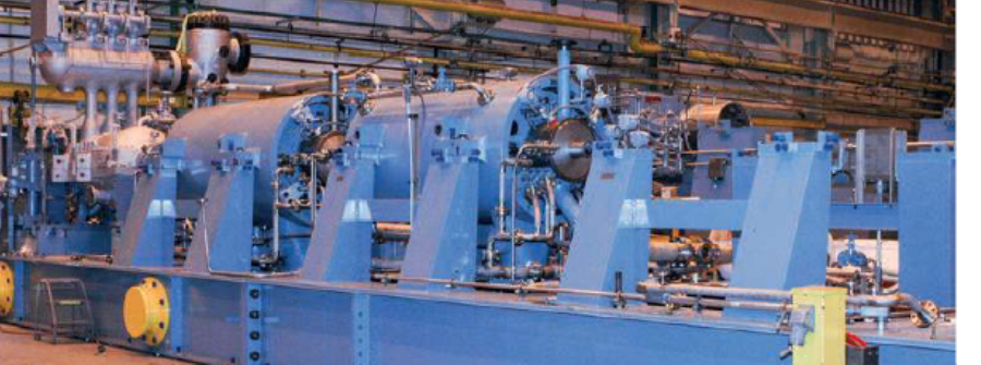
  • Steam path optimization is applicable to special steam turbines used in oil & gas facilities, power generation plants, combined cycle plants, and cogeneration plants.
  • It can be implemented in various turbine configurations, including extraction, backpressure, condensing, and reheat turbines.
  1. What:
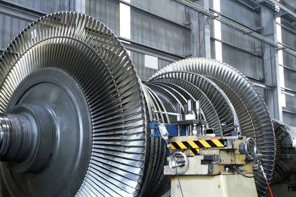
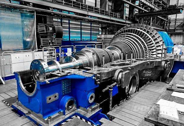
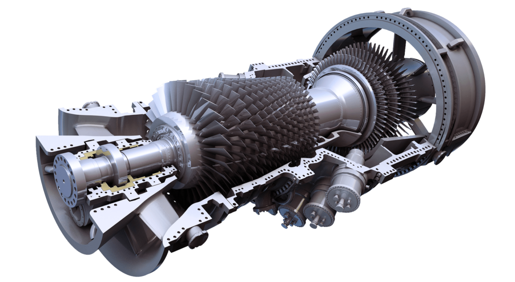
  • Steam path optimization involves optimizing the flow path geometry, blade profiles, inlet and outlet areas, and internal cooling systems of the turbine.
  • It includes evaluating and improving aspects such as blade aerodynamics, steam flow distribution, velocity profiles, and blade surface cooling.
  1. Which:
  • The selection of specific optimization techniques and methods depends on the turbine design, operating conditions, and goals of the steam path optimization.
  • Consideration should be given to factors such as blade shape, twist angle, aspect ratio, steam expansion, and control of secondary flow effects.
  1. How:
  • Conduct a thorough assessment of the existing steam path design, performance data, and operational conditions.
  • Utilize advanced computational fluid dynamics (CFD) modeling and simulation techniques to analyze and optimize the flow path geometry and aerodynamics.
  • Consider blade design modifications, such as profiling, twist, or stacking, to enhance efficiency and reduce losses.
  • Evaluate and optimize the cooling systems to ensure proper blade temperature distribution and minimize thermal stresses.
  • Perform performance testing and validation to verify the improvements achieved through steam path optimization.
  • Collaborate with turbine manufacturers, engineering consultants, and experts in steam turbine design and optimization for guidance and expertise.
  • Comply with relevant international standards, codes, and regulations, ensuring safety, environmental compliance, and performance requirements.

It is important to note that steam path optimization is a specialized and complex process that requires expertise in steam turbine design, fluid dynamics, and computational modeling. Collaboration with experienced professionals and adherence to industry best practices are crucial to successfully achieve the desired high reliability, availability, safety, and operational performance in special steam turbines.

Courtesy by ANSALDO

PROCEDURES, ACTIONS, STUDIES, ANALYSIS, MITIGATIONS AND RECOMMENDATIONS TO GET STEAM PATH OPTIMIZATION IN SPECIAL STEAM TURBINES

  1. Procedures:
  • Develop a comprehensive steam path optimization procedure that outlines the steps, responsibilities, and criteria for evaluating and optimizing the turbine’s flow path.
  • Define a clear process for data collection, performance assessment, design modifications, and verification of the optimized steam path.
  1. Actions:
  • Gather operational data and performance information of the existing steam turbine to establish a baseline for evaluation.
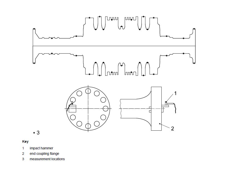
  • Conduct detailed inspections and measurements of the turbine components, including blade profiles, clearances, and cooling systems.
  • Collaborate with turbine manufacturers, engineering consultants, and experts to gain insights into turbine design, performance, and optimization techniques.
  1. Studies and Analysis:
  • Perform computational fluid dynamics (CFD) simulations to analyze the flow path, aerodynamics, and thermal characteristics of the turbine.
  • Utilize CFD modeling to identify areas of flow separation, high turbulence, or inefficient energy conversion within the steam path.
  • Conduct sensitivity analyses to evaluate the impact of design modifications on turbine performance and efficiency.
  1. Design Modifications:
  • Optimize blade profiles, stacking, and twist angles to improve aerodynamic efficiency and reduce losses.
  • Enhance internal cooling systems to improve blade temperature distribution and minimize thermal stresses.
  • Optimize inlet and outlet areas, as well as nozzle and diaphragm designs, to ensure smooth and efficient flow transitions.
  1. Performance Testing and Verification:
  • Conduct performance testing and validation to verify the improvements achieved through steam path optimization.
  • Measure key performance indicators, such as turbine efficiency, power output, and steam consumption, to assess the effectiveness of the optimization efforts.
  • Compare the optimized turbine’s performance with the baseline data to evaluate the achieved reliability, availability, and operational performance.
  1. Mitigations:
  • Address any potential risks associated with design modifications, such as blade vibrations, resonance, or increased thermal stresses.
  • Implement appropriate mitigations based on the findings of structural and dynamic analyses to ensure safe and reliable turbine operation.
  • Conduct risk assessments and hazard analyses to identify potential safety risks and propose suitable mitigation strategies.
  1. Recommendations:
  • Regularly monitor and maintain the optimized steam path to ensure continued high performance and reliability.
  • Incorporate advanced condition monitoring and predictive maintenance techniques to detect and address any early signs of performance degradation or component issues.
  • Stay updated with industry advancements and best practices in steam turbine design and optimization to continuously improve performance and operational efficiency.

It is important to note that steam path optimization for special steam turbines is a complex and specialized field that requires expertise in turbine design, fluid dynamics, and computational modeling. Collaboration with experienced turbine manufacturers, engineering consultants, and industry experts is crucial to navigate these procedures, analyses, mitigations, and recommendations effectively, ensuring the achievement of high reliability, availability, safety, and operational performance.

Consulting – BEST OPTION FOR CENTRIFUGAL COMPRESSORS IN GAS PIPELINES AND GAS DISTRIBUTION

BEST OPTION TO SELECT CENTRIFUGAL COMPRESSORS IN GAS PIPELINES AND GAS DISTRIBUTION SYSTEMS

Courtesy by SOLAR

TECHNICAL REQUIREMENTS TO SELECT CENTRIFUGAL COMPRESSORS IN GAS PIPELINES AND GAS DISTRIBUTION SYSTEMS

  1. Flow Capacity: The compressor should have the appropriate flow capacity to meet the gas flow rate requirements of the pipeline or distribution system. This involves considering factors such as anticipated gas demand, pipeline diameter, and pressure drop limitations.

  2. Pressure Ratio: The compressor should be capable of achieving the required pressure ratio to maintain the desired gas pressure throughout the pipeline or distribution network. Consideration should be given to factors such as inlet pressure, outlet pressure, and potential pressure variations along the system.

  3. Efficiency: Select a compressor with high efficiency to minimize energy consumption and operating costs. Look for compressors with optimal isentropic efficiency, which indicates how well the compressor converts input power into compressed gas output.

  4. Reliability and Availability: Consider the compressor’s reliability and availability track record. Look for equipment from reputable manufacturers with a proven history of reliable operation in similar applications. Redundancy features, such as dual compressor trains, can improve system availability.

  5. Maintainability: Evaluate the ease of maintenance and access to key components for inspection, repair, and routine maintenance activities. Consider features that allow for quick and efficient maintenance, such as easily removable panels, accessible bearings, and standardized components.

  6. Safety Features: Choose compressors with integrated safety features and systems to mitigate safety risks. These can include emergency shutdown systems, safety relief valves, vibration monitoring systems, and gas detection systems. Compliance with industry safety standards and regulations is essential.

  7. Environmental Considerations: Consider the environmental impact of the compressor, including emissions control and noise reduction. Choose compressors that meet applicable environmental regulations and standards, minimizing the impact on the environment and surrounding communities.

  8. Control and Monitoring Systems: Ensure compatibility with control and monitoring systems used in the oil & gas and petrochemical industry. Integration with distributed control systems (DCS) and plant-wide monitoring systems enables efficient control, real-time monitoring, and data analysis.

  9. Compliance with Standards: Select compressors that comply with international industry standards, such as API (American Petroleum Institute) standards, ISO (International Organization for Standardization) codes, and relevant safety regulations.

  10. System Integration: Consider how the compressor will integrate into the overall pipeline or distribution system. Assess compatibility with existing infrastructure, control systems, and safety systems to ensure seamless integration and optimal performance.

It is important to consult with experienced engineering consultants, equipment manufacturers, and industry experts to determine the specific technical requirements based on the unique characteristics of the gas pipeline or distribution system. Collaborative efforts will help ensure the selection of the best centrifugal gas compressor that meets the requirements of reliability, availability, maintainability, safety, and operational performance in the oil & gas and petrochemical industry.

LIMITATIONS IN ENGINEERING & DESIGN OF CENTRIFUGAL COMPRESSORS IN GAS PIPELINES AND GAS DISTRIBUTION SYSTEMS

  1. Space Constraints: Gas pipeline and distribution systems often have limited space available for compressor installation. Space limitations may impact the selection of compressor models and their associated equipment, such as auxiliary systems and control panels. Finding an optimal layout that accommodates the required equipment while ensuring accessibility and safety can be challenging.

  2. Environmental Factors: Gas pipeline and distribution systems are subject to various environmental conditions, such as extreme temperatures, humidity, and corrosive atmospheres. These factors may impose constraints on the selection of compressor materials, coatings, and protection systems to ensure long-term reliability and performance in harsh environments.

  3. Operating Conditions: Each gas pipeline and distribution system has specific operating conditions, including pressure ranges, temperature variations, and gas composition. Compressors must be selected to operate within these conditions to ensure reliable and efficient performance. Deviations from specified operating conditions may impact compressor efficiency, reliability, and safety.

  4. Gas Composition: Gas composition variations in different regions or sources can present challenges in compressor selection. Different gases may require different materials of construction, sealing systems, and compressor designs. Consideration must be given to the compatibility of the compressor with the gas composition to ensure reliable operation and avoid any adverse effects on equipment performance.

  5. Turndown Ratio: Turndown ratio refers to the range over which the compressor can adjust its output capacity while maintaining efficiency and performance. Compressors with limited turndown ratios may struggle to meet varying demands in gas pipeline and distribution systems. Limitations in turndown ratio may impact the ability to optimize operational performance and efficiency.

  6. Cost Constraints: Cost considerations, including capital expenditure and lifecycle costs, can impose limitations on the selection of centrifugal gas compressors. High-performance compressors with advanced features may come at a higher cost. Balancing the desired level of reliability, availability, maintainability, safety, and operational performance with budgetary constraints can be a challenge.

  7. System Compatibility: Compressor selection should take into account compatibility with existing infrastructure, control systems, and safety systems in gas pipeline and distribution systems. Integration challenges may arise if the selected compressor is not compatible with the existing system components, requiring additional engineering efforts and potential modifications.

  8. Future Flexibility: Anticipating future changes in demand, system expansions, or modifications is critical in compressor selection. The selected compressor should be flexible enough to accommodate future changes without compromising system performance, reliability, or safety. Limitations in the flexibility of the chosen compressor may require costly modifications or replacements in the future.

It is essential to engage experienced engineering consultants, equipment manufacturers, and industry experts during the selection process to navigate these limitations effectively. Their expertise will help identify and address potential constraints, ensuring the optimal selection of centrifugal gas compressors for gas pipeline and distribution systems in the oil & gas and petrochemical industry.

Courtesy by BORSIG

WHY, WHEN, WHERE, WHAT, WHICH AND HOW TO SELECT CENTRIFUGSL COMPRESSORS IN GAS PIPELINES AND GAS DISTRIBUTION SYSTEMS

  1. Why:
  • Selecting the best centrifugal gas compressor ensures reliable gas compression, maintaining the required pressure and flow rates in gas pipeline and distribution systems.
  • It helps enhance system efficiency, minimize downtime, and optimize overall operational performance.
  1. When:
  • The selection process takes place during the design and planning stages of the gas pipeline or distribution system.
  • It can also be necessary when upgrading or expanding an existing system or replacing aging or inefficient compressors.
  1. Where:
  • The selection applies to gas pipeline and distribution systems within the oil & gas and petrochemical industry, including onshore and offshore installations.
  • It can be relevant for both short-distance and long-distance pipelines, as well as distribution networks serving residential, commercial, or industrial consumers.
  1. What:
  • The selection involves identifying the specific requirements of the gas pipeline or distribution system, such as flow capacity, pressure range, gas composition, and environmental conditions.
  • It encompasses evaluating the performance characteristics, such as efficiency, reliability, maintainability, and safety features, of different centrifugal gas compressor models.
  1. Which:
  • Choose a centrifugal gas compressor model that best meets the specific requirements and performance criteria of the gas pipeline or distribution system.
  • Consider factors such as flow capacity, pressure range, efficiency, reliability track record, maintainability features, safety systems, and compliance with industry standards.
  1. How:
  • Engage experienced engineering consultants, equipment manufacturers, and industry experts to assess the technical requirements and specifications of the gas pipeline or distribution system.
  • Conduct feasibility studies, engineering analyses, and system simulations to determine the optimal compressor size, configuration, and control systems.
  • Evaluate the compressor’s performance characteristics, efficiency curves, and operating range to ensure compatibility with the system requirements.
  • Consider factors such as reliability track record, maintenance requirements, spare parts availability, and ease of access for routine maintenance and inspection.
  • Assess safety features, compliance with regulations, and environmental considerations, such as emissions control and noise reduction.
  • Integrate the selected compressor into the gas pipeline or distribution system, ensuring compatibility with control systems and safety interlocks.
  • Follow proper installation, commissioning, and ongoing maintenance practices to ensure optimal performance, reliability, and safety.

By following this approach, taking into account the unique requirements of the gas pipeline or distribution system, one can select the best centrifugal gas compressor that improves reliability, availability, maintainability, safety, and operational performance in the oil & gas and petrochemical industry.

PROCEDURES, ACTIONS, STUDIES, ANALYSIS, MITIGATIONS AND RECOMMENDATIONS TO SELECT CENTRIFUGAL COMPRESSORS IN GAS PIPELINES AND GAS DISTRIBUTION SYSTEMS

  1. Procedures:
  • Develop a comprehensive selection procedure that outlines the steps, responsibilities, and criteria for evaluating and choosing the best centrifugal gas compressor.
  • Establish guidelines for data collection, assessment of system requirements, performance evaluation, and compliance with industry standards and regulations.
  • Define a clear process for evaluating and comparing different compressor models based on key factors such as flow capacity, pressure ratio, efficiency, reliability, maintainability, and safety features.
  1. Actions:
  • Conduct a detailed assessment of the gas pipeline or distribution system requirements, including flow capacity, pressure range, gas composition, temperature, and environmental conditions.
  • Engage with qualified engineering consultants, equipment suppliers, and industry experts to gain insights and access to the latest compressor technologies and innovations.
  • Request information and technical specifications from compressor manufacturers to evaluate their offerings and capabilities.
  • Consider site-specific factors, such as available space, noise restrictions, and installation considerations, to ensure a proper fit for the compressor within the system.
  1. Studies and Analysis:
  • Perform feasibility studies and engineering analyses to determine the optimal compressor size, configuration, and control systems for the gas pipeline or distribution system.
  • Conduct system-level simulations and modeling to assess the performance, efficiency, and pressure characteristics of the compressor under varying operating conditions.
  • Perform risk assessments and hazard analyses to identify potential safety risks associated with the compressor operation and propose suitable mitigations.
  • Conduct reliability studies, such as failure mode and effects analysis (FMEA), to identify potential failure modes, their impact, and develop strategies to mitigate them.
  1. Mitigations:
  • Ensure redundancy and backup systems for critical components to minimize the impact of equipment failures on system reliability and availability.
  • Implement safety measures such as emergency shutdown systems, safety relief valves, and gas detection systems to mitigate safety risks.
  • Consider implementing condition monitoring systems for real-time monitoring of compressor performance, vibration, and health to detect anomalies and plan maintenance activities proactively.
  1. Recommendations:
  • Ensure compliance with international standards and industry best practices throughout the selection process, including adherence to API (American Petroleum Institute) standards and ISO (International Organization for Standardization) codes.
  • Regularly review and update maintenance procedures based on operational experience and equipment performance.
  • Foster a strong safety culture within the organization, promoting proper training, clear communication, and adherence to safety protocols.
  • Establish a comprehensive maintenance program that includes routine inspections, preventive maintenance, and timely repairs or replacements of critical components.

It is essential to tailor these procedures, actions, studies, analyses, mitigations, and recommendations to the specific requirements and characteristics of the gas pipeline or distribution system. Collaboration with experienced engineering consultants, equipment suppliers, and compliance experts is crucial to ensuring the successful selection of the best centrifugal gas compressor that enhances reliability, availability, maintainability, safety, and operational performance in the oil & gas and petrochemical industry.

Consulting – BEST OPTION TO SELECT CENTRIFUGAL GAS COMPRESSORS FOR LNG PLANTS

BEST OPTION TO SELECT CENTRIFUGAL GAS COMPRESSORS FOR LNG PLANTS

Courtesy by ELLIOTT

TECHNICAL REQUIREMENTS TO SELECT A CENTRIFUGAL GAS COMPRESSORS IN LNG PLANTS

  1. Compliance with Standards and Regulations:
  • Adherence to international standards and codes specific to gas compressors, such as API (American Petroleum Institute) standards, ISO (International Organization for Standardization) standards, and ASME (American Society of Mechanical Engineers) codes.
  • Compliance with relevant safety regulations and guidelines, including those related to hazardous areas, fire protection, and explosion prevention.
  • Compliance with environmental regulations, including emissions limits and noise control requirements.
  1. Design and Construction:
  • Robust and reliable design suitable for the demanding operating conditions of an LNG plant, including high-pressure and cryogenic environments.
  • Materials selection considering the corrosion resistance required for handling natural gas and other process gases in the LNG plant.
  • Compliance with equipment design codes and standards specific to the LNG industry, such as those set by LNG equipment associations and regulatory bodies.
  • Consideration of seismic requirements and other site-specific factors.
  1. Reliability and Availability:
  • Proven track record and a history of successful operation in similar LNG plant applications.
  • High mean time between failures (MTBF) and low mean time to repair (MTTR) to maximize reliability and minimize downtime.
  • Implementation of redundancy and backup systems to ensure continuous operation and minimize the risk of unplanned outages.
  • Availability of reliable spare parts and a robust supply chain to support maintenance and repair needs.
  1. Maintainability:
  • Accessibility of key components and ease of maintenance to minimize downtime during planned maintenance activities.
  • Availability of technical documentation, including operation manuals, maintenance procedures, and troubleshooting guides.
  • Compatibility with condition monitoring systems to enable proactive maintenance and early fault detection.
  • Integration with computerized maintenance management systems (CMMS) for efficient maintenance planning and execution.
  1. Safety and Environmental Considerations:
  • Incorporation of safety features, such as emergency shutdown systems, interlocks, and safety instrumented systems (SIS), to prevent accidents and ensure personnel safety.
  • Implementation of robust protection systems against fire, explosion, and gas leaks, including gas detection and emergency ventilation.
  • Compliance with environmental regulations, including emissions control measures and noise reduction strategies.
  • Minimization of potential environmental impacts through the use of efficient designs, waste management practices, and appropriate noise control measures.
  1. Operational Performance:
  • High compression efficiency to maximize the gas compression process efficiency and minimize energy consumption.
  • Consideration of turndown capabilities to match varying process demands and maintain stable operation.
  • Compatibility with the control and automation systems of the LNG plant, including integration with the distributed control system (DCS) and supervisory control and data acquisition (SCADA) systems.

It is crucial to consult with experienced engineering consultants, equipment manufacturers, and subject matter experts in LNG plant design and operation to ensure compliance with the best international regulations, standards, and current technical specifications. This collaborative approach will help in selecting centrifugal gas compressors that meet the stringent technical requirements for reliability, availability, maintainability, safety, and operational performance, while mitigating safety risks and minimizing environmental impacts in an LNG plant.

LIMITATIONS IN ENGINEERING & DESIGN FOR CENTRIFUGAL COMPRESSORS IN LNG PLNTS

  1. Cost: Engineering and design choices that optimize all desired aspects can sometimes come at a higher cost. Balancing budget constraints with the desired performance and safety features can be a challenge.

  2. Space Limitations: LNG plants often have limited space, and this can impact the selection and arrangement of equipment, including centrifugal gas compressors. Finding an optimal layout that accommodates the required equipment while maintaining accessibility and safety may pose limitations.

  3. Complexity: Achieving the highest level of reliability, availability, and operational performance may require more complex engineering and design solutions. This can lead to increased maintenance and operational complexities, requiring specialized skills and training for the plant operators and maintenance personnel.

  4. System Integration: Integrating the selected centrifugal gas compressors into the overall LNG plant system can present challenges. Ensuring compatibility and seamless integration with other equipment, control systems, and safety systems may require additional engineering effort.

  5. Environmental Constraints: LNG plants operate under stringent environmental regulations. The selection of gas compressors must consider emissions control and noise reduction requirements. Meeting these constraints while maintaining optimal performance can be a limitation in the engineering and design process.

  6. Safety Considerations: While safety is a priority, certain design choices may impact operational performance or efficiency. Balancing safety requirements with performance targets can pose challenges that need careful consideration during the engineering and design phase.

  7. Future Expansion and Flexibility: Anticipating future expansion and changes in operational requirements is essential. Design choices need to be flexible enough to accommodate future modifications or expansions without compromising the reliability, availability, and safety of the gas compressor system.

It is important to engage experienced engineers, design consultants, and equipment manufacturers who have expertise in LNG plant design to navigate these limitations effectively. Their knowledge and experience can help in making informed decisions that strike the right balance between reliability, availability, maintainability, safety, operational performance, environmental impact, and compliance with regulations and standards.

Courtesy by HITACHI

WHY, WHEN, WHERE, WHAT, WHICH AND HOW TO USE CENTRIFUGAL COMPRESSORS IN LNG PLANTS

Why:

  • Centrifugal gas compressors are used in LNG plants to compress natural gas for transportation, storage, and liquefaction processes.
  • They play a crucial role in maintaining the required pressure levels and flow rates for efficient LNG production and transportation.

When:

  • Centrifugal gas compressors are used in LNG plants during various stages, including gas pre-treatment, liquefaction, refrigeration, and regasification processes.
  • They are typically installed at different points in the LNG plant, such as inlet compression, boil-off gas compression, and LNG vaporization.

Where:

  • LNG plants worldwide utilize centrifugal gas compressors to optimize the efficiency and reliability of the liquefaction and regasification processes.
  • They are commonly found in both onshore and offshore LNG facilities.

What:

  • Centrifugal gas compressors are mechanical devices that use centrifugal force to compress and raise the pressure of natural gas.
  • They consist of key components such as an impeller, diffuser, volute, and various auxiliary systems for lubrication, cooling, and control.

Which:

  • Selection of the appropriate centrifugal gas compressor depends on factors such as gas flow rates, pressure ratios, process requirements, and site-specific conditions.
  • It is essential to choose a compressor model that meets the specific design parameters and technical specifications outlined by international regulations and standards.

How:

  • Engage experienced engineering consultants and equipment suppliers to assess the technical requirements and specifications of the LNG plant.
  • Conduct a thorough evaluation of available centrifugal gas compressor options, considering factors such as reliability, availability, maintainability, safety, and operational performance.
  • Ensure compliance with international regulations and standards, such as API (American Petroleum Institute) standards and ISO (International Organization for Standardization) codes.
  • Conduct detailed engineering and design reviews, including safety and environmental considerations, to select the most suitable centrifugal gas compressor.
  • Integrate the selected compressor into the LNG plant system, considering layout, system compatibility, and safety interlocks.
  • Follow proper installation, commissioning, and ongoing maintenance practices to ensure optimal performance and reliability.

Remember, the specific details of the why, when, where, what, which, and how of using centrifugal gas compressors in an LNG plant will depend on the unique characteristics and requirements of the plant itself, as well as local regulations and industry best practices. Consulting with experts in LNG plant design and operation is crucial for successful implementation.

PROCEDURES, ACTIONS, STUDIES, ANALYSIS, MITIGATIONS AND RECOMMENDATIONS TO USE CENTRIFUGAL COMPRESSORS IN LNG PLANTS

  1. Procedures:
  • Develop comprehensive procedures for the selection, installation, and operation of centrifugal gas compressors in the LNG plant.
  • Establish clear procedures for routine maintenance, inspection, and troubleshooting of compressors.
  • Implement proper procedures for start-up, shutdown, and emergency handling of compressors.
  1. Actions:
  • Perform a detailed assessment of the specific process requirements and operating conditions to identify the appropriate compressor specifications and performance criteria.
  • Engage qualified engineering consultants and equipment suppliers with expertise in LNG plant design and compressor selection.
  • Conduct thorough site assessments to ensure proper foundation and infrastructure for compressor installation.
  • Establish a comprehensive maintenance program that includes regular inspections, condition monitoring, and preventive maintenance activities.
  1. Studies and Analysis:
  • Conduct feasibility studies and engineering analyses to determine the optimal compressor size, configuration, and control systems for the LNG plant’s specific requirements.
  • Perform system-level simulations and modeling to assess the performance and efficiency of the gas compression process.
  • Conduct risk assessments and hazard analyses to identify potential safety risks and develop appropriate mitigation strategies.
  • Perform reliability studies, such as failure mode and effects analysis (FMEA), to identify potential failure modes and develop strategies to mitigate them.
  1. Mitigations:
  • Implement redundancy in critical components and systems to ensure continuous operation and minimize the impact of equipment failures.
  • Incorporate safety features and systems, such as emergency shutdown systems and gas detection systems, to mitigate safety risks.
  • Establish proper ventilation and gas dispersion systems to address potential leakage or release scenarios.
  • Implement condition monitoring systems to detect early signs of equipment degradation or impending failures.
  1. Recommendations:
  • Ensure compliance with international regulations, standards, and industry best practices throughout the selection, installation, and operation of centrifugal gas compressors.
  • Regularly review and update maintenance procedures based on operational experience and equipment performance.
  • Foster a strong safety culture within the LNG plant, promoting proper training, clear communication, and adherence to safety protocols.
  • Continuously monitor and evaluate compressor performance, reliability, and efficiency to identify opportunities for improvement and optimization.

It is important to note that the specific procedures, actions, studies, analyses, mitigations, and recommendations will depend on the unique characteristics of the LNG plant, local regulations, and industry best practices. Collaboration with experienced engineering consultants, equipment suppliers, and compliance experts is crucial to ensure the successful implementation of centrifugal gas compressors in an LNG plant while meeting the highest standards of reliability, availability, maintainability, safety, and operational performance while minimizing environmental impacts.

Consulting – ADVANCED CONTROL SYSTEMS (MODEL PREDICTIVE CONTROL (MPC), FUZZY LOGIC CONTROL AND SIMILAR TECHNOLOGY) – TURBOMACHINERY

ADVANCED CONTROL SYSTEMS (MODEL PREDICTIVE CONTROL (MPC), FUZZY LOGIC CONTROL, NEURAL NETWORKS AND SIMILAR TECHNOLOGY) - TURBOMACHINERY

CENTRIFUGAL COMPRESSORS

GAS TURBINES

SPECIAL STEAM TURBINES

Advanced control systems, including model predictive control (MPC), fuzzy logic control, and other similar technologies, have played a significant role in improving the dynamic response and operational flexibility of turbomachinery, such as centrifugal compressors, gas turbines, and special steam turbines. These control systems utilize advanced algorithms, data-driven models, and intelligent decision-making to optimize the operation of turbomachinery and enhance reliability, safety, and performance. Here’s an overview of the key control systems and their impact:

  1. Model Predictive Control (MPC): Model Predictive Control is a sophisticated control technique that utilizes mathematical models of the turbomachinery system to predict its future behavior and optimize control actions. MPC considers system dynamics, constraints, and objectives to generate optimal control strategies. Benefits of MPC in turbomachinery include:
  • Enhanced Stability: MPC accounts for system dynamics and can handle complex and nonlinear behavior, improving stability and response time.
  • Optimization of Multiple Objectives: MPC optimizes multiple objectives, such as efficiency, emissions, and reliability, simultaneously, allowing for better operational flexibility and performance trade-offs.
  • Constraint Handling: MPC incorporates constraints, such as equipment limits and safety limits, in the control strategy, ensuring safe and reliable operation even during abnormal conditions.
  • Robustness: MPC can handle uncertainties and disturbances by adapting the control actions in real-time, leading to improved robustness and performance.
  1. Fuzzy Logic Control: Fuzzy Logic Control (FLC) is a control methodology that utilizes linguistic rules based on expert knowledge to make control decisions. FLC is particularly useful in turbomachinery applications where precise mathematical models may not be available or the system behavior is complex. Benefits of FLC in turbomachinery include:
  • Adaptability: FLC can handle nonlinearities and uncertainties, making it suitable for controlling turbomachinery with varying operating conditions and complex dynamics.
  • Expert Knowledge Incorporation: FLC allows operators to incorporate their domain expertise through linguistic rules, capturing their knowledge of the system behavior and control actions.
  • Fault Detection and Tolerance: FLC can incorporate fault detection and tolerance mechanisms, allowing for continued operation even in the presence of certain faults or abnormal conditions.
  • Transparency: FLC provides interpretability as linguistic rules are easily understandable, enabling operators to have insight into the control actions and decisions.
  1. Other Advanced Control Technologies: Other advanced control technologies, such as adaptive control, neural networks, and fuzzy-neural hybrid control, have also been applied in turbomachinery to improve reliability, safety, and performance. These technologies offer benefits such as adaptive tuning, learning capabilities, and increased robustness to disturbances and uncertainties.

Implementation considerations and recommendations:

  • Accurate Modeling: Developing accurate mathematical models or data-driven models of the turbomachinery system is crucial for the effectiveness of advanced control systems. Models should capture the relevant dynamics, non-linearities, and operating conditions.
  • Real-time Data Integration: Real-time sensor data integration into the control system enables continuous monitoring of system variables, facilitating adaptive and dynamic control actions.
  • System Identification: System identification techniques can be employed to identify and validate the dynamic behavior of the turbomachinery system, improving the accuracy and reliability of control algorithms.
  • Operator Training: Operators and control engineers should receive appropriate training to understand the advanced control systems, their tuning, and operation, enabling effective utilization and optimization.
  • Continuous Monitoring and Maintenance: Regular monitoring, performance evaluation, and maintenance of the advanced control systems are necessary to ensure their continued effectiveness and adaptability to changing operating conditions.

By leveraging advanced control systems like MPC, FLC, and other similar technologies, turbomachinery operators can achieve improved dynamic response, operational flexibility, and performance, leading to enhanced reliability, safety, and overall equipment performance in applications such as centrifugal compressors, gas turbines, and special steam turbines.

ADVANTAGES & DISADVANTAGES USING ADVANCED CONTROL SYSTEMS IN TURBOMACHINERY

Advantages:

  1. Enhanced Dynamic Response: Advanced control systems can improve the dynamic response of turbomachinery by accounting for system dynamics, non-linearities, and constraints. They enable faster and more accurate control actions, leading to improved stability, faster load changes, and reduced response time.

  2. Optimized Performance: These control systems facilitate optimization of multiple objectives, such as efficiency, emissions, and reliability. They consider complex operating conditions, constraints, and objectives simultaneously, allowing for better operational flexibility and trade-offs to achieve optimal performance.

  3. Adaptive and Robust Control: Advanced control systems, like neural networks and fuzzy-neural hybrid control, offer adaptive capabilities to handle varying operating conditions and uncertainties. They can self-adjust and learn from data, enabling robust control actions in the presence of disturbances or parameter variations.

  4. Fault Detection and Tolerance: Certain advanced control systems, including fuzzy logic control and neural networks, can incorporate fault detection and tolerance mechanisms. This enables the system to detect and respond to faults or abnormal conditions, allowing for continued safe and reliable operation.

  5. Expert Knowledge Incorporation: Fuzzy logic control and similar techniques allow operators to incorporate their domain expertise through linguistic rules. This facilitates the utilization of expert knowledge to guide control actions, making the control system more intuitive and transparent.

Disadvantages:

  1. Model Complexity and Design Effort: Developing accurate mathematical models or data-driven models for advanced control systems can be complex and time-consuming. It requires a deep understanding of system dynamics, non-linearities, and operating conditions, as well as significant effort in model development and tuning.

  2. Model Accuracy and Adaptability: The accuracy and adaptability of the control system depend on the quality and accuracy of the underlying models. If the models do not accurately represent the system behavior or fail to capture variations and uncertainties, the control system’s effectiveness may be compromised.

  3. Tuning and Parameter Optimization: Proper tuning and optimization of the advanced control system parameters are crucial for optimal performance. This process can be challenging and may require extensive experience, expertise, and iterative adjustments to achieve the desired performance.

  4. Computational Requirements: Advanced control systems, particularly model predictive control and neural networks, may have higher computational requirements. Real-time processing and optimization can be demanding, requiring sufficient computational resources to handle the complex calculations involved.

  5. Interpretability and Transparency: Some advanced control systems, such as neural networks, can lack interpretability and transparency. The inner workings of the control algorithm may be challenging to understand, making it difficult for operators to interpret and validate the control actions and decisions.

It’s important to note that the advantages and disadvantages mentioned above are general considerations, and the specific implementation and performance of advanced control systems may vary based on the application, system complexity, available data, and expertise of the operators. Careful design, tuning, validation, and continuous monitoring are necessary to maximize the advantages and mitigate the limitations of advanced control systems in turbomachinery applications.

Courtesy by SOLAR
Courtesy by GE
Courtesy by SHIN

WHY, WHEN, WHERE, WHAT, WHICH, HOW TO USE ADVANCED CONTROL SYSTEMS IN TURBOMACHINERY

Why use advanced control systems?

  • Advanced control systems offer several benefits, including improved dynamic response, optimized performance, adaptive and robust control, fault detection and tolerance, and expert knowledge incorporation. These benefits help achieve higher reliability, safety, and performance in turbomachinery systems.

When to use advanced control systems?

  • Advanced control systems are particularly useful in situations where precise control, fast response, and optimal performance are crucial. They are employed during normal operations and challenging conditions when the system dynamics and constraints require advanced algorithms and decision-making to maintain safe and efficient operation.

Where are advanced control systems used?

  • Advanced control systems can be applied in various industries, including the oil & gas sector, power generation plants, chemical processing facilities, and other industrial environments that utilize turbomachinery. They are used in onshore and offshore installations where high-performance control and operational flexibility are necessary.

What can be accomplished with advanced control systems?

  • Advanced control systems can improve the dynamic response and operational flexibility of turbomachinery by optimizing performance, ensuring stability, reducing response time, adapting to varying operating conditions, handling uncertainties, and incorporating expert knowledge. They contribute to enhanced reliability, safety, and overall performance of the equipment.

Which components can benefit from advanced control systems?

  • Advanced control systems can be applied to various components of turbomachinery, including compressors, turbines, combustion systems, and associated control systems. They address the control and optimization requirements of these components to improve their dynamic response and operational performance.

How are advanced control systems implemented?

  • The implementation of advanced control systems involves the following steps: (1) Developing accurate mathematical models or data-driven models of the turbomachinery system; (2) Designing and tuning the control algorithms based on the specific control objectives, system dynamics, and constraints; (3) Integrating real-time data acquisition systems for monitoring and control; (4) Validating and testing the control system performance using simulations and real-world data; (5) Fine-tuning and optimizing control parameters based on operational experience and feedback.

It’s important to note that the selection and implementation of specific advanced control systems depend on the unique characteristics of the turbomachinery, control objectives, available resources, and expertise of the operators. Detailed analysis, system understanding, and consideration of operational requirements are necessary for successful implementation and achievement of the desired improvements in reliability, safety, and performance.

PROCEDURES, ACTIONS, STUDIES, ANALYSIS, MITIGATION AND RECOMMENDATIONS TO USE ADVANCED CONTROL SYSTEMS IN TURBOMACHINERY

  1. Procedures and Actions:
  • System Analysis: Conduct a thorough analysis of the turbomachinery system, including the components, operating conditions, constraints, and control objectives.
  • Control System Design: Select the appropriate advanced control system, such as MPC, fuzzy logic control, neural networks, or fuzzy-neural hybrid control, based on the specific requirements and characteristics of the turbomachinery system.
  • Model Development: Develop accurate mathematical models or data-driven models of the turbomachinery system, considering system dynamics, non-linearities, and uncertainties.
  • Controller Tuning: Determine the optimal parameters and tuning of the control algorithms to achieve the desired control objectives, stability, and performance.
  • Integration of Real-Time Data: Implement data acquisition systems and integrate real-time data from sensors to enable monitoring and control actions.
  • Validation and Testing: Validate and test the control system performance using simulations, hardware-in-the-loop testing, or real-world data to ensure its effectiveness and stability.
  • Implementation and Deployment: Deploy the advanced control system in the turbomachinery system, including integration with existing control infrastructure, communication networks, and monitoring systems.
  • Monitoring and Maintenance: Continuously monitor the performance of the advanced control system and conduct regular maintenance activities to ensure its continued effectiveness and adaptability.
  1. Studies and Analysis:
  • System Dynamics and Modeling: Conduct studies to understand the system dynamics and develop accurate mathematical models or data-driven models of the turbomachinery system.
  • Control Strategy Optimization: Perform optimization studies to determine the optimal control strategies, tuning parameters, and set-points for improved dynamic response and operational flexibility.
  • Performance Evaluation: Analyze the performance of the advanced control system using simulations and real-world data, comparing it with baseline control strategies or reference models.
  • Fault Detection and Diagnosis: Study and analyze methods for incorporating fault detection and diagnosis capabilities into the control system to enhance reliability and safety.
  • Robustness Analysis: Conduct robustness analysis to evaluate the performance and adaptability of the advanced control system under varying operating conditions, uncertainties, and disturbances.
  1. Mitigations and Recommendations:
  • Operator Training: Provide training to operators and control engineers on the implementation, operation, and maintenance of advanced control systems to ensure proper utilization and effective monitoring.
  • Data Quality Assurance: Implement data quality assurance processes to ensure the accuracy, reliability, and completeness of the data used in the control system, including sensor calibration and validation.
  • Cybersecurity Measures: Establish robust cybersecurity measures to protect the integrity, confidentiality, and availability of the control system and associated data.
  • Continuous Monitoring and Optimization: Continuously monitor the performance of the advanced control system, collect operational data, and analyze its effectiveness. Implement optimization techniques to further enhance the performance and adaptability of the control system.
  • Collaboration and Knowledge Sharing: Foster collaboration among industry stakeholders, control system developers, researchers, and equipment manufacturers to share best practices, insights, and lessons learned in implementing advanced control systems.

It’s important to note that the specific procedures, actions, studies, analyses, mitigations, and recommendations may vary based on the specific advanced control system selected, the characteristics of the turbomachinery system, and industry-specific requirements. Close collaboration with domain experts, control system developers, and equipment manufacturers is crucial for successful implementation and to achieve the desired improvements in reliability, safety, and performance.

Consulting – DIGITAL TWIN TECHNOLOGY IN TURBOMACHINERY

DIGITAL TWIN TECHNOLOGY IN TURBOMACHINERY

CENTRIFUGAL COMPRESSORS

GAS TURBINES

SPECIAL STEAM TURBINES

Here’s how digital twin technology works and its benefits:

  1. Creation of Virtual Replicas: Digital twins utilize sensor data from the physical turbomachinery equipment to create a virtual replica or model. This virtual representation captures the geometry, operating parameters, and behavior of the actual equipment, providing a real-time digital counterpart.

  2. Real-Time Monitoring and Data Integration: Digital twins continuously collect and integrate real-time data from sensors installed on the physical equipment. This data includes parameters such as temperature, pressure, vibration, and performance metrics. By analyzing this data, operators gain insights into the current operating conditions, health status, and performance of the turbomachinery.

  3. Predictive Analytics and Condition Monitoring: By combining the real-time data with physics-based models and advanced analytics algorithms, digital twins enable predictive analytics and condition monitoring. The digital twin can detect anomalies, identify potential issues or failures, and predict equipment behavior, allowing for proactive maintenance and optimization of operational parameters.

  4. Performance Optimization and Simulation: Digital twins facilitate the analysis and optimization of turbomachinery performance. Operators can simulate different operating scenarios and evaluate the impact on efficiency, emissions, and reliability. This capability enables fine-tuning of operational parameters, control strategies, and maintenance schedules to enhance overall performance and safety.

  5. Remote Monitoring and Diagnostics: Digital twin technology enables remote monitoring and diagnostics of turbomachinery equipment. Operators can access the digital twin from anywhere and analyze the performance and health status of the equipment in real-time. Remote diagnostics allow for prompt identification of issues, troubleshooting, and timely decision-making to improve reliability and minimize downtime.

  6. Proactive Maintenance and Lifecycle Management: By continuously monitoring the equipment’s condition, digital twins enable proactive maintenance strategies. They provide insights into the remaining useful life of components, trigger maintenance alerts based on predictive analytics, and optimize maintenance schedules to reduce unplanned downtime and extend the equipment’s operational life.

  7. Enhanced Safety and Risk Management: Digital twins contribute to enhanced safety and risk management by simulating and analyzing various safety scenarios. They help identify potential hazards, evaluate the impact of failures or abnormalities, and optimize safety measures. By understanding and mitigating risks, operators can ensure the safety of personnel and equipment.

Overall, digital twin technology offers significant benefits in improving the reliability, safety, and operational performance of turbomachinery in the oil & gas industry and power generation plants. It enables real-time monitoring, predictive analytics, performance optimization, remote diagnostics, proactive maintenance, and enhanced safety measures. By leveraging the digital twin, operators can make informed decisions, optimize operations, and minimize risks associated with turbomachinery equipment.

ADVANTAGES & DISADVANTAGES USING DIGITAL TWIN TECHNOLOGY IN TURBOMACHINERY

Advantages:

  1. Real-Time Monitoring: Digital twins enable real-time monitoring of turbomachinery equipment, providing operators with up-to-date information on operating conditions, performance, and health status. This real-time insight allows for proactive decision-making and prompt action to address potential issues, leading to improved reliability and reduced downtime.

  2. Predictive Maintenance: Digital twins leverage data analytics and predictive modeling to anticipate potential failures or abnormalities in turbomachinery equipment. By identifying early warning signs, operators can schedule maintenance activities in advance, optimize maintenance resources, and minimize unscheduled downtime, resulting in improved reliability and availability.

  3. Performance Optimization: Digital twins facilitate performance optimization by simulating different operating scenarios and analyzing their impact on efficiency, emissions, and overall performance. Operators can fine-tune operational parameters, control strategies, and maintenance schedules to achieve optimal performance, enhancing efficiency and reducing operational costs.

  4. Remote Monitoring and Diagnostics: Digital twins enable remote monitoring and diagnostics of turbomachinery equipment. Operators can access the digital twin from anywhere, analyze equipment performance, and diagnose potential issues remotely. This capability reduces the need for on-site inspections, improves response times, and enhances safety by minimizing human intervention in hazardous environments.

  5. Enhanced Safety and Risk Management: Digital twins contribute to improved safety and risk management by simulating and analyzing safety scenarios. They help identify potential hazards, evaluate the impact of failures, and optimize safety measures. This capability enhances safety protocols, reduces risks to personnel and equipment, and improves overall operational safety.

Disadvantages:

  1. Data Integration and Complexity: Implementing digital twin technology requires integration of various data sources and systems, which can be complex and time-consuming. It involves capturing, processing, and analyzing large volumes of real-time data from sensors and other sources. The complexity of data integration and system setup may pose challenges during implementation.

  2. Cost and Infrastructure Requirements: Building and maintaining digital twins necessitates investments in infrastructure, data storage, computational resources, and analytics capabilities. The costs associated with developing and maintaining the digital twin platform can be significant, making it a potential barrier to adoption for some organizations.

  3. Data Privacy and Security: Digital twins rely on the collection and analysis of sensitive operational data. Protecting this data from unauthorized access, cybersecurity threats, and potential breaches is crucial. Implementing robust data privacy and security measures is essential to mitigate risks and maintain the integrity and confidentiality of the data.

  4. Model Accuracy and Validation: The accuracy and reliability of the digital twin depend on the quality of the underlying physics-based models, data inputs, and validation processes. Ensuring accurate models and reliable data inputs requires ongoing validation and calibration against real-world operating conditions. Inaccurate models or inadequate validation can undermine the effectiveness of the digital twin.

  5. Organizational Adaptation: Integrating digital twin technology into existing workflows and processes may require changes to organizational culture, practices, and skills. This adaptation includes training personnel to effectively use and interpret digital twin outputs, embracing new data-driven approaches, and fostering a culture of continuous improvement.

It’s important to note that while digital twin technology offers significant advantages, its implementation should consider the specific needs, resources, and challenges of each organization. Addressing the potential disadvantages through careful planning, data governance, validation processes, and organizational readiness can help maximize the benefits of digital twin technology in turbomachinery applications.

LIMITATIONS IN ENGINEERING & DESIGN TO USE DIGITAL TWIN TECHNOLOGY IN TURBOMACHINERY

  1. Model Complexity and Accuracy: Developing accurate physics-based models for digital twins can be challenging, particularly for complex turbomachinery systems. Accurate representation of fluid dynamics, combustion processes, and interactions between components requires detailed knowledge of the equipment and accurate modeling assumptions. Achieving high-fidelity models that accurately capture real-world behavior can be demanding and time-consuming.

  2. Data Availability and Quality: Digital twins rely on real-time data from sensors installed on the turbomachinery equipment. However, there may be limitations in data availability, particularly in older or legacy equipment that lacks integrated sensor networks. Additionally, data quality issues such as noise, inconsistencies, or gaps can impact the accuracy and reliability of the digital twin model.

  3. Data Integration and Compatibility: Integrating data from various sources and systems into the digital twin platform can be challenging. Different sensors, data formats, and protocols may require data integration and conversion efforts. Ensuring compatibility and seamless integration of data from diverse sources can be complex and may require additional data preprocessing and integration infrastructure.

  4. Calibration and Validation: Validating and calibrating the digital twin model against real-world operating conditions is critical to ensure accuracy and reliability. This process requires access to comprehensive and representative operational data, which may not always be readily available. Proper calibration and validation are essential to ensure the digital twin provides meaningful insights and reliable predictions.

  5. Computational Requirements: The simulation and analysis involved in digital twin technology require significant computational resources. High-performance computing capabilities may be necessary to handle the complex modeling and real-time data processing requirements of digital twins. Organizations must ensure sufficient computational infrastructure and resources to support the computational demands of digital twin applications.

  6. Organizational Readiness: Implementing digital twin technology involves organizational readiness and capabilities. Organizations need to develop the necessary skills, expertise, and processes to effectively leverage the digital twin outputs and incorporate them into decision-making processes. This includes training personnel, establishing data governance frameworks, and integrating digital twin practices into existing engineering and design workflows.

  7. Cost Considerations: Developing and maintaining a digital twin platform involves costs associated with data acquisition, sensor installation, computational resources, and software development. The initial investment and ongoing operational costs should be carefully evaluated against the expected benefits and the specific needs of the organization.

Despite these limitations, ongoing advancements in technology, data analytics, and modeling techniques continue to address these challenges. As digital twin technology evolves, researchers and industry experts are actively working to overcome these limitations and further enhance the engineering and design applications of digital twins in turbomachinery for improved reliability, safety, and operational performance.

Courtesy by SIEMENS
Courtesy by ANSALDO
Courtesy by MHI

WHY, WHEN, WHERE, WHAT, WHICH AND HOW TO USE DIGITAL TWIN TECHNOLOGY IN TURBOMACHINERY

Why use digital twin technology?

  • Digital twin technology offers several benefits, including real-time monitoring, predictive maintenance, performance optimization, remote diagnostics, and enhanced safety. These advantages enable operators to make data-driven decisions, optimize equipment performance, and minimize downtime, ultimately improving reliability, safety, and operational efficiency.

When to use digital twin technology?

  • Digital twin technology can be used throughout the lifecycle of turbomachinery equipment, including the design, manufacturing, operation, and maintenance stages. It is particularly beneficial during operation and maintenance phases when real-time monitoring, predictive maintenance, and performance optimization are critical for ensuring reliable and safe equipment operation.

Where is digital twin technology used?

  • Digital twin technology is applied in various settings, including oil & gas facilities, power generation plants, and other industrial facilities that utilize turbomachinery. It can be used in both onshore and offshore installations, including remote and challenging environments where real-time monitoring and diagnostics are valuable.

What can be accomplished with digital twin technology?

  • With digital twin technology, operators can create virtual replicas of turbomachinery equipment, monitor real-time operating conditions, predict equipment behavior, optimize performance, and enable remote diagnostics. It facilitates proactive maintenance, enhances safety, and improves overall operational performance by providing insights into equipment health and performance.

Which components can be represented in a digital twin?

  • Digital twins can represent various components of turbomachinery, including blades, rotors, stators, casings, combustion chambers, and associated control systems. These components play crucial roles in the reliable and safe operation of centrifugal compressors, gas turbines, and steam turbines.

How is digital twin technology implemented?

  • The implementation of digital twin technology involves integrating real-time data from sensors installed on the physical equipment and coupling it with physics-based models, simulations, and analytics algorithms. This integration creates a virtual replica that can be monitored, analyzed, and simulated to optimize performance, predict failures, and enable proactive maintenance.

It’s important to note that the specific application of digital twin technology in turbomachinery can vary depending on the specific needs, operating conditions, and industry requirements. Each implementation requires careful consideration of the available data sources, modeling techniques, data integration, and computational infrastructure to ensure effective deployment and achieve the desired improvements in reliability, safety, and operational performance.

PROCEDURES, ACTIONS, STUDIES, ANALYSIS, MITIGATION AND RECOMMENDATION TO USE DIGITAL TWIN TECHNOLOGY IN TURBOMACHINERY

When using digital twin technology in turbomachinery, such as centrifugal compressors, gas turbines, and steam turbines, to improve reliability, safety, and operational performance in the oil & gas industry and power generation plants, several procedures, actions, studies, analyses, mitigations, and recommendations should be considered. Here’s an overview of key considerations:

  1. Procedures and Actions:
  • Data Acquisition: Install appropriate sensors and data acquisition systems to collect real-time data on operating conditions, performance parameters, and health indicators of the turbomachinery equipment.
  • Data Integration: Develop a robust data integration framework to collect, process, and integrate data from various sources, ensuring compatibility and accuracy.
  • Model Development: Create physics-based models that accurately represent the behavior, dynamics, and interactions of the turbomachinery equipment. This includes fluid dynamics, combustion processes, and structural dynamics.
  • Real-Time Data Processing: Implement real-time data processing and analytics capabilities to analyze incoming data, detect anomalies, and identify potential issues or performance deviations.
  • Visualization and User Interface: Develop user-friendly interfaces and visualizations that allow operators to monitor and interact with the digital twin, providing insights into equipment performance and health status.
  1. Studies and Analysis:
  • Failure Mode and Effects Analysis (FMEA): Conduct FMEA to identify potential failure modes, assess their severity, and develop mitigation strategies to enhance reliability and safety.
  • Performance Optimization: Utilize simulations and optimization techniques to analyze different operating scenarios, control strategies, and maintenance schedules to optimize performance and efficiency.
  • Prognostics and Health Management: Implement prognostics and health management techniques to predict the remaining useful life of components, detect early signs of degradation, and enable proactive maintenance actions.
  • Risk Assessment: Perform risk assessments to identify and mitigate safety hazards associated with the turbomachinery equipment and develop appropriate safety measures.
  1. Mitigations and Recommendations:
  • Data Quality Assurance: Implement quality assurance processes to ensure the accuracy, reliability, and completeness of the data used in the digital twin. This includes data validation, cleansing, and calibration against known reference values.
  • Cybersecurity Measures: Establish robust cybersecurity measures to protect the integrity, confidentiality, and availability of data within the digital twin system.
  • Continuous Model Calibration: Regularly validate and calibrate the digital twin model against real-world operating conditions to ensure accuracy and reliability.
  • Proactive Maintenance Strategies: Utilize the insights provided by the digital twin to implement proactive maintenance strategies, including condition-based monitoring, predictive maintenance, and optimized maintenance scheduling.
  • Personnel Training: Provide training to operators and maintenance personnel to effectively use and interpret the outputs of the digital twin system. This includes understanding the data, models, and analysis techniques used within the digital twin framework.
  • Collaboration and Knowledge Sharing: Foster collaboration among stakeholders, including equipment manufacturers, operators, and research institutions, to share best practices, insights, and lessons learned in digital twin implementation.

It’s important to note that the specific procedures, actions, studies, analyses, mitigations, and recommendations may vary based on the unique characteristics of the turbomachinery, the selected digital twin technologies, and the industry standards and regulations applicable to the oil & gas industry and power generation plants. Therefore, it is crucial to conduct comprehensive research, engage with domain experts, and adhere to relevant guidelines and standards throughout the implementation and utilization of digital twin technology in turbomachinery.

Consulting – ADDITIVE MANUFACTURING (3D PRINTING) – TURBOMACHINERY

ADDITIVE MANUFACTURING (3D PRINTING) - TURBOMACHINERY

Courtesy by SUNDYNE
Courtesy by BAKER HUGHES
Courtesy by MHI

CENTRIFUGAL COMPRESSORS

GAS TURBINES

SPECIAL STEAM TURBINES

  1. Complex Geometries: Additive manufacturing enables the production of highly complex geometries that were traditionally challenging or impossible to manufacture using conventional methods. Turbomachinery components, such as blades, vanes, and impellers, can be designed with intricate internal cooling channels, optimized aerodynamic profiles, and tailored shapes for improved performance. These complex geometries enhance reliability by optimizing fluid flow, reducing turbulence, and minimizing stress concentrations.

  2. Lightweight Design: Additive manufacturing allows for the creation of lightweight structures without compromising strength or performance. By optimizing the component’s internal lattice structures or using topology optimization algorithms, it’s possible to reduce the weight of turbomachinery parts, resulting in reduced inertia, improved efficiency, and increased power-to-weight ratio. Lighter components can also lead to reduced mechanical loads and wear on supporting structures and bearings, enhancing overall reliability.

  3. Customization and Rapid Prototyping: Additive manufacturing facilitates customization and rapid prototyping of turbomachinery components. This capability allows engineers to quickly iterate designs, test new concepts, and optimize performance based on specific requirements. By enabling rapid prototyping, additive manufacturing accelerates the development process, reduces lead times, and enhances the overall design quality, leading to improved reliability and safety.

  4. Material Flexibility: Additive manufacturing offers a wide range of materials suitable for turbomachinery applications, including high-temperature alloys, superalloys, and metal matrix composites. These materials provide excellent mechanical properties, temperature resistance, and corrosion resistance required for demanding operating conditions in the oil & gas industry and power generation plants. The ability to select materials tailored to specific applications improves reliability, durability, and safety.

  5. Reduced Assembly and Part Count: Additive manufacturing allows for the consolidation of multiple parts into a single component. By integrating several individual pieces into a single 3D-printed part, assembly time and potential points of failure are reduced. Fewer joints and interfaces minimize the risk of leaks, misalignments, and structural weaknesses, thereby improving reliability and safety.

  6. Repair and Maintenance: Additive manufacturing offers the capability to repair or replace damaged or worn-out turbomachinery components more efficiently. Instead of sourcing and waiting for replacement parts, 3D printing enables on-demand production of spare parts, reducing downtime and improving the availability of equipment. This capability is particularly advantageous in remote locations where spare parts may not be readily available.

  7. Improved Cooling and Heat Transfer: Additive manufacturing allows for the creation of intricate internal cooling channels within turbomachinery components. These channels enhance the cooling capacity of blades, vanes, and other critical parts, enabling better heat dissipation and reducing the risk of thermal damage. Improved cooling leads to enhanced reliability and safety by preventing component degradation and extending their operational life.

Overall, additive manufacturing in turbomachinery provides opportunities for design optimization, lightweighting, customization, rapid prototyping, and efficient repair. These benefits contribute to improved reliability, safety, and operational performance in the oil & gas industry and power generation plants by enhancing component efficiency, reducing downtime, and enabling more effective maintenance strategies.

ADVANTAGES & DISADVANTAGES APPLYING ADDITIVE MANUFACTURING (3D PRINTING) IN TURBOMACHINERY

Advantages:

  1. Design Flexibility: Additive manufacturing allows for the creation of complex geometries and intricate internal structures that are difficult or impossible to achieve with traditional manufacturing methods. This flexibility enables the optimization of component designs for improved performance, efficiency, and reliability.

  2. Customization and Rapid Prototyping: Additive manufacturing enables the production of customized components tailored to specific applications or operating conditions. It also allows for rapid prototyping, facilitating iterative design improvements, reducing development time, and enhancing reliability and safety through quicker validation and testing.

  3. Lightweight Design: By utilizing advanced lattice structures and topology optimization, additive manufacturing can produce lightweight components without sacrificing strength. Lighter parts reduce inertia, improve efficiency, and decrease mechanical loads on supporting structures, leading to enhanced reliability and operational performance.

  4. Reduced Assembly and Part Count: Additive manufacturing enables the consolidation of multiple parts into a single component, reducing assembly time and the number of potential failure points. Fewer joints and interfaces minimize the risk of leaks, misalignments, and structural weaknesses, enhancing reliability and safety.

  5. On-Demand Manufacturing and Repair: Additive manufacturing facilitates on-demand production of spare parts, reducing downtime and improving equipment availability. It also enables efficient repair by replacing damaged or worn-out components without the need for complex supply chains. This capability enhances reliability and operational performance, particularly in remote locations.

Disadvantages:

  1. Material Limitations: While additive manufacturing offers a wide range of materials suitable for turbomachinery applications, certain specialized alloys and composites may not be readily available or feasible to 3D print. Material limitations can impact the performance, durability, and reliability of components.

  2. Quality Control and Certification: Ensuring consistent quality and adherence to industry standards can be challenging in additive manufacturing. Stringent quality control processes and certification procedures are necessary to guarantee the reliability and safety of 3D-printed components, which may involve additional time and cost considerations.

  3. Limited Size and Scalability: Additive manufacturing currently faces limitations in terms of component size and scalability. Producing large-scale turbomachinery parts using 3D printing can be technically challenging and time-consuming. This constraint may restrict the application of additive manufacturing in certain turbomachinery systems.

  4. Surface Finish and Post-Processing: 3D-printed parts may exhibit rougher surface finishes compared to components produced through traditional manufacturing techniques. Additional post-processing steps, such as machining or surface treatments, may be required to achieve the desired surface quality, introducing additional time, cost, and complexity.

  5. Cost Considerations: While additive manufacturing can offer benefits in terms of customization and reduced assembly, the initial setup and equipment costs for implementing 3D printing can be significant. Additionally, depending on the specific application and volume requirements, the cost of 3D-printed components may be higher than those produced using conventional methods.

  6. Process Validation and Optimization: Implementing additive manufacturing in turbomachinery requires thorough process validation and optimization to ensure consistent quality, repeatability, and reliability. The development of suitable process parameters, material selection, and post-processing techniques can be time-consuming and resource-intensive.

It’s important to note that the advantages and disadvantages of additive manufacturing in turbomachinery may vary depending on the specific application, operating conditions, and industry requirements. As technology continues to advance, ongoing research and development efforts aim to address these challenges and expand the use of additive manufacturing in turbomachinery for improved reliability, safety, and operational performance.

Courtesy by MAN
Courtesy by SOLAR TURBINES
Courtesy by DE PETTRO

LIMITATIONS APPLYING ADDITIVE MANUFACTURING (3D PRINTING) IN TURBOMACHINERY

  1. Size Constraints: Additive manufacturing techniques currently face limitations in terms of the size of components that can be printed. Turbomachinery parts, such as large impellers or rotors, may exceed the maximum build volume of 3D printers. This limitation restricts the application of additive manufacturing to smaller or less complex components, potentially limiting its impact on overall system performance.

  2. Material Selection: While there is a wide range of materials available for additive manufacturing, certain specialized alloys or composites used in turbomachinery may not be suitable for 3D printing. Materials with specific mechanical properties, high-temperature resistance, or corrosion resistance may have limited options in additive manufacturing, affecting the overall reliability and operational performance of the equipment.

  3. Manufacturing Time: Additive manufacturing can be a time-consuming process, particularly for larger or complex components. The layer-by-layer printing method can result in longer production times compared to conventional manufacturing methods. This limitation can impact the availability and turnaround time for producing or repairing critical turbomachinery components.

  4. Surface Finish and Post-Processing: 3D-printed components often exhibit rougher surface finishes compared to those produced through traditional manufacturing methods. Additional post-processing steps, such as machining or surface treatments, may be required to achieve the desired surface quality and dimensional accuracy. These additional steps can introduce complexity, cost, and potential variability in the final product.

  5. Quality Control and Certification: Ensuring consistent quality and meeting industry standards can be challenging in additive manufacturing. Stringent quality control processes and certification procedures are necessary to guarantee the reliability and safety of 3D-printed turbomachinery components. Developing and implementing quality assurance protocols specific to additive manufacturing can be time-consuming and resource-intensive.

  6. Cost Considerations: While additive manufacturing can offer benefits in terms of customization and reduced assembly, it can be a costly manufacturing method. The initial setup and equipment costs for implementing 3D printing can be significant. Additionally, depending on the specific application and volume requirements, the cost of 3D-printed components may be higher than those produced using conventional methods, impacting the economic feasibility of widespread adoption.

  7. Process Validation and Optimization: Implementing additive manufacturing in turbomachinery requires rigorous process validation and optimization to ensure consistent quality and repeatability. Identifying suitable process parameters, validating material properties, and optimizing printing techniques can be complex and time-consuming. These challenges can delay the adoption of additive manufacturing in critical turbomachinery applications.

It’s worth noting that ongoing advancements in additive manufacturing technology and materials research aim to address these limitations. As the technology evolves, researchers and industry experts are actively working to overcome these challenges and expand the applications of additive manufacturing in turbomachinery, ultimately enhancing reliability, safety, and operational performance in the oil & gas industry and power generation plants.

WHY, WHEN, WHERE, WHAT, WHICH, AND HOW TO APPLY ADDITIVE MANUFACTURING (3D PRINTING) IN TURBOMACHINERY

Why apply additive manufacturing?

  • Additive manufacturing offers several advantages such as design flexibility, customization, rapid prototyping, lightweight design, and on-demand manufacturing/repair. These benefits can enhance the reliability, safety, and operational performance of turbomachinery by optimizing component designs, reducing weight, improving efficiency, enabling customization, and minimizing downtime through efficient repair processes.

When to apply additive manufacturing?

  • Additive manufacturing can be applied during different stages of the turbomachinery lifecycle, including initial design, prototyping, production, and maintenance/repair. It can be used when there is a need for complex geometries, customization, quick design iterations, lightweight structures, on-demand spare parts, or efficient repair processes.

Where is additive manufacturing used?

  • Additive manufacturing can be utilized in various settings, including manufacturing facilities, research and development labs, and maintenance/repair facilities for turbomachinery. It can be applied in both onshore and offshore oil & gas facilities, power generation plants, and any other industry that utilizes turbomachinery.

What components can be 3D printed?

  • Additive manufacturing can be used to produce various components of turbomachinery, including blades, vanes, impellers, casings, combustion chambers, and cooling channels. These components are critical for the reliable and safe operation of centrifugal compressors, gas turbines, and special steam turbines.

Which materials can be used?

  • A wide range of materials can be used in additive manufacturing for turbomachinery. This includes high-temperature alloys, superalloys, metal matrix composites, and other specialized materials suitable for turbomachinery applications. Material selection depends on factors such as mechanical properties, temperature resistance, corrosion resistance, and specific operating conditions.

How is additive manufacturing applied?

  • The application of additive manufacturing involves several steps, including component design using computer-aided design (CAD) software, selection of suitable materials, optimization of build parameters, 3D printing using additive manufacturing machines, post-processing (such as machining or surface treatments), and quality control/validation to ensure reliability and safety.

Overall, additive manufacturing is applied in turbomachinery to address specific needs such as design optimization, customization, lightweighting, rapid prototyping, on-demand manufacturing/repair, and improved efficiency. It can be utilized at different stages of the turbomachinery lifecycle and in various settings to enhance reliability, safety, and operational performance in the oil & gas industry and power generation plants.

PROCEDURES, ACTIONS, STUDIES, ANALYSIS, MITIGATION AND RECOMMENDATIONS OF APPLYING ADDITIVE MANUFACTURING (3D PRINTING) IN TURBOMACHINERY

  1. Procedures and Actions:
  • Design Validation: Thoroughly validate the additive manufacturing design through simulations, prototyping, and testing to ensure it meets performance and safety requirements.
  • Material Selection: Carefully select materials suitable for turbomachinery applications, considering mechanical properties, high-temperature resistance, and corrosion resistance.
  • Process Optimization: Optimize additive manufacturing parameters, such as printing speed, layer thickness, and heat treatment, to achieve desired material properties and quality.
  • Post-Processing: Implement appropriate post-processing techniques, such as machining or surface treatments, to achieve required surface finish and dimensional accuracy.
  • Quality Control and Validation: Establish rigorous quality control procedures to ensure consistent quality and compliance with industry standards. Validate the printed components through non-destructive testing and performance assessments.
  1. Studies and Analysis:
  • Material Characterization: Conduct material characterization studies to understand the properties and behavior of additive manufacturing materials under relevant operating conditions.
  • Failure Mode and Effects Analysis (FMEA): Perform FMEA to identify potential failure modes, assess their severity, and develop mitigation strategies to enhance reliability and safety.
  • Computational Fluid Dynamics (CFD): Utilize CFD simulations to study fluid flow patterns, pressure distributions, and temperature profiles within the turbomachinery components to optimize performance and mitigate potential issues.
  • Finite Element Analysis (FEA): Perform FEA to evaluate stress, strain, and deformation in critical components, ensuring structural integrity and identifying areas for design improvements.
  1. Mitigations and Recommendations:
  • Robust Design: Optimize the design of additive manufacturing components to minimize stress concentrations, improve fluid dynamics, and enhance reliability under varying operating conditions.
  • Material Testing and Certification: Conduct thorough material testing and certification processes to ensure material properties meet required standards and specifications.
  • In-Service Monitoring: Implement condition monitoring systems to detect early signs of degradation or failure and enable proactive maintenance actions.
  • Training and Knowledge Transfer: Train personnel involved in additive manufacturing processes to ensure their proficiency in handling and operating the equipment, as well as understanding potential risks and best practices.
  • Collaboration and Industry Standards: Foster collaboration among industry stakeholders, regulatory bodies, and research institutions to develop industry standards, guidelines, and best practices specific to additive manufacturing in turbomachinery.

It’s essential to note that the specific procedures, actions, studies, analyses, mitigations, and recommendations may vary based on the unique characteristics of the turbomachinery, the selected additive manufacturing technologies, and the industry standards and regulations applicable to the oil & gas industry and power generation plants. Therefore, it is crucial to conduct comprehensive research, engage with domain experts, and adhere to relevant guidelines and standards throughout the application of additive manufacturing in turbomachinery.

Consulting – TORSIONAL VIBRATION MEASUREMENT TECHNIQUES IN TURBOMACHINERY

TORSIONAL VIBRATION MEASUREMENT TECHNIQUES IN TURBOMACHINERY

Courtesy by SIEMENS
Courtesy by DOOSAN

GAS TURBINES

SPECIAL STEAM TURBINES

A variety of different measurement techniques have been successfully employed in the past to measure the torsional vibration characteristics of coupled shaft systems. These methods are subject to continuous improvement; therefore, which is most appropriate for a specific application will depend on several factors. This section provides further background to some of these measurement techniques. It is emphasized that these are not the only available methods and there are some other equally applicable methods developed by the different OEMs.

TORSIONAL VIBRATION TRANSDUCERS

The following devices may be used as torsional vibration transducers:

a) eddy current probes, inductive probes, lasers, etc. (non-contacting transducers);

b) strain gauges;

c) optical decoders;

d) accelerometers positioned circumferentially at specified angles (preferably at 0° and 180°).

Other methods may be used by agreement between the customer and set supplier.

MEASUREMENT PARAMETERS

Depending upon the method of measurement, it is recommended that the following be included in the test report:

a) rotational velocity of the shaft system;

b) turbine generator set power output;

c) torsional vibration magnitude;

d) torsional strain;

e) ambient temperature of test site;

f) torsional natural frequency;

g) speed range over which measurements are carried out.

An additional parameter that can influence the torsional vibration is

h) blade-disc coupled nodal diameter frequency.

Other parameters can be measured on agreement between the customer and set supplier.

Courtesy by GE
Courtesy by ANSALDO

FACTORY STATIC TESTS ON STATIONARY ROTORS

“Modal tests” may be performed on rotors in their static (i.e. non-rotating) configuration in the factory. This is one way of measuring mode shapes and natural frequencies under static conditions.
They provide verification of predicted behaviour and, therefore, help to calibrate shaft system models for fundamental rotor body and overhang modes under stationary conditions. In recognition of the fact that boundary conditions influence the final outcome of the test, it is important either
to carry out a free-free test or to support test rotors on bearing journals with hard rubber or similar supports. These supports provide little resistance to the impact energy path at the contact areas so that the relevant torsional modes of the rotor under test are properly captured in the
frequency spectrum.

When blades are mounted on rotors, a perfect contact between blade roots and the main rotor body may not always be achievable when the rotor is stationary, due to the design of root employed or manufacturing tolerances. As a result, the impact energy imparted by a test hammer to the structure may be disrupted at the blade-rotor body contact areas, making it difficult to capture blade-disc and rotor coupled frequencies and their associated modes. Even if such modes are captured in the test, they are less useful because the blade-disc frequencies will continuously change with speed. 
In other words, the blades dynamically couple with the rotor and this will continue until rated speed is reached. This coupling effect, along with stress stiffening due to speed, creates new sets of torsional frequencies that are different from individual blade and disc alone frequencies under
stationary conditions. Similar difficulties exist when carrying out static tests on generator rotors due to the influence of the copper windings and associated wedges.

Therefore, although static “modal tests” are helpful to calibrate rotor body models, they do not generally provide an accurate assessment of the frequencies of either the blade-disc coupled system or the generator body modes that vary with speed. Full speed (dynamic) factory or site tests are necessary to assess these effects.
Figure below shows the arrangement for a typical factory static rotor test.

ON-SITE TORSION TEST (CASE FOR TURBINES IN POWER PLANTS)

Depending on the type of mode that is critical, a field test could involve measurements at a few locations or be performed on a more elaborate scale. The choice of measurement positions is normally determined by examination of the predicted mode shapes, but in most cases the measuring of torsional vibration magnitudes at two locations, such as the turbine to generator shaft region and the permanent magnet generator, is sufficient to capture the important turbine and generator coupled rotor and blade modes. However, if more detailed mode shapes are required, it can be necessary to measure torsional response at other locations on the shaft or at the blade tips.

In order to measure torsional natural frequencies at a power plant site, it is necessary to provide a means of detecting torsional vibration at one or more locations along the shaft. This can be done by various means: toothed wheels and magnetic or proximity transducers, painted or taped stripes and optical transducers, permanent magnet generator (PMG) voltage signals, strain gauges, etc. The demodulated torsional signals are then usually displayed on a spectrum analyzer to determine their various frequency components. Although it requires more effort, utilizing multiple measuring locations is an advantage because they can potentially identify more torsional modes and because their relative magnitudes at each natural frequency enable the measurement of mode shapes.

When a turbine generator is assembled at a power plant site, it becomes a challenge to measure torsional natural frequencies, particularly those in the vicinity of twice line frequency. 
Sub-synchronous (below-line frequency) torsional natural frequencies can typically be easily measured with the unit on-line, as they are usually excited to measurable levels by random power system fluctuations. If necessary, synchronization or line switching tests can be done to excite
these sub-synchronous torsional modes. Such techniques, however, may not be successful in exciting and measuring super-synchronous (above-line frequency) torsional natural frequencies with much confidence. This is why in the mid-1970s the off-line torsional frequency response test
was developed.

An off-line torsional frequency response test involves exciting the generator in a controlled manner using oscillatory torque developed from unbalanced currents flowing in the generator stator.
These unbalanced currents are obtained by the application of a line-to-neutral short circuit test connection on the high-voltage side of the generator main step-up transformer (or, alternatively, a line-to-line connection at the generator terminals) while the unit is shut down and not connected to the grid. With the turbine generator running at various speeds, a small amount of field excitation is applied to the generator, which induces unbalanced or negative sequence current in the generator. The field excitation is applied in a controlled amount small enough not to exceed the negative sequence current heating limits of the generator but large enough such that the induced negative sequence currents can excite shaft system natural frequencies to measurable levels at resonance.

The generator air gap torque induced by these negative sequence currents occurs at a frequency equal to twice the electrical frequency of the generator. By changing the speed of the generator during this test (possible because the generator is off-line), the electrical frequency and thus
the frequency of the air gap torque also changes. Thus, by slowly ramping the speed, a slow sweep of the air gap torque frequency is obtained. In this manner, torsional natural frequencies can be detected by the occurrence of resonant peaks in the torsional response as the speed is ramped.
Later in the test, the speed can be held at each of these resonant peaks in order to measure precisely the torsional natural frequency, and also to confirm that the measured response is indeed due to torsion, by removing the field excitation (and thus the air gap torque) and observing that the response magnitude changes accordingly.

For several years, the off-line frequency test was the only reliable method of accurately identifying the torsional natural frequencies of the fully installed unit at site. However, with the increasing sophistication of signal analysis techniques, it is now possible to detect all frequencies of interest by measuring the effects of small transient disturbances that occur under normal operation. These disturbances, which are a consequence of the minor random disturbances that are inevitably present on all electrical networks, cause transient excitation of those natural modes that can be excited by the generator. The advantage of this technique for the customer is that, other than the time required to install the measurement equipment, there is no impact on the normal operation of the power plant.

Consulting – PRESSURE FLUCTUATIONS IN COMBUSTION SYSTEM – GAS TURBINES

PRESSURE FLUCTUATIONS IN THE COMBUSTION SYSTEM - GAS TURBINES

Courtesy by DAIHATSU

In gas turbines, pressure fluctuations in the combustion system can occur due to various factors, including flame pulsations. Flame pulsations refer to the periodic variations in the size, shape, or intensity of the flame. These pulsations can lead to fluctuations in the combustion process, which can result in several issues, including excessive mechanical stress, mechanical resonance, and combustion problems such as lean flame. Here’s an explanation of these aspects:

  1. Excessive Mechanical Stress:

    • Flame pulsations can cause rapid changes in heat release rates and localized variations in temperature and pressure within the combustion system.
    • These rapid changes in thermal and mechanical loading can result in excessive mechanical stress on the turbine components, such as the combustion chamber walls, transition ducts, and fuel nozzles.
    • Excessive mechanical stress can lead to material fatigue, deformation, and premature failure of these components, compromising the reliability and longevity of the gas turbine.
  2. Mechanical Resonance:

    • Mechanical resonance can occur when the natural frequency of the combustion system or its components coincides with the frequency of the flame pulsations.
    • If the flame pulsation frequency matches the natural frequency of the combustion system, resonance amplifies the pressure fluctuations and mechanical stress, exacerbating the problem.
    • Mechanical resonance can lead to significant vibrations and increased mechanical loading, which can result in structural damage, decreased component life, and potential safety risks.
  3. Lean Flame Combustion Problems:

    • Lean flame conditions refer to the operation of the gas turbine with a fuel-air mixture that has a relatively low fuel-to-air ratio.
    • Flame pulsations can be more pronounced in lean flame conditions due to the increased sensitivity of lean flames to combustion instability.
    • Lean flame combustion problems associated with flame pulsations can include flame blowout, flashback, or combustion instability, leading to reduced combustion efficiency, increased emissions, and potential equipment damage.

Analyzing pressure fluctuations associated with flame pulsations and addressing the associated risks requires several considerations:

  • Monitoring Techniques: Utilize pressure sensors, dynamic flame sensors, and other instrumentation to monitor flame behavior and pressure fluctuations within the combustion system.
  • Combustion Stability Analysis: Conduct comprehensive combustion stability analysis to identify the causes and characteristics of flame pulsations. This can involve experimental measurements, computational modeling, and data analysis techniques.
  • System Design and Optimization: Ensure that the combustion system design and operational parameters are optimized to minimize the risk of flame pulsations. This may include appropriate fuel injection patterns, chamber geometry, and flame stabilization mechanisms.
  • Fuel-Air Ratio Control: Maintain an appropriate fuel-air ratio to avoid lean flame conditions that can increase the likelihood of flame pulsations.
  • Active Control Systems: Consider implementing active control strategies, such as fuel modulation or flame stabilization techniques, to dampen flame pulsations and mitigate the associated risks.
  • Material Selection and Component Design: Utilize materials and component designs that can withstand the mechanical stress caused by flame pulsations, considering factors such as thermal expansion, vibration resistance, and fatigue strength.
  • Ongoing Monitoring and Maintenance: Implement regular monitoring and maintenance programs to detect and address any emerging issues related to pressure fluctuations and flame pulsations.

By understanding and addressing pressure fluctuations associated with flame pulsations, gas turbine operators can mitigate the risks of excessive mechanical stress, mechanical resonance, and lean flame combustion problems. This leads to improved operational reliability, reduced maintenance costs, and enhanced combustion performance in gas turbines.

LIMITATIONS IN ENGINEERING & DESIGN TO AVOID PRESSURE FLUCTUATIONS IN THE COMBUSTION SYSTEMS

When it comes to avoiding and controlling pressure fluctuations in the combustion system of gas turbines, particularly those associated with flame pulsations and the risks of excessive mechanical stress, mechanical resonance, and combustion problems such as lean flame, there are certain limitations in engineering and design that need to be considered:

  1. Complex Combustion Dynamics: The combustion process in gas turbines is complex, involving intricate interactions between fuel, air, and combustion products. It can be challenging to accurately predict and control flame pulsations and their associated pressure fluctuations due to the complex nature of combustion dynamics.

  2. Sensitivity to Operating Conditions: Pressure fluctuations, flame pulsations, and the associated risks are often sensitive to changes in operating conditions such as fuel composition, load variations, and environmental factors. Achieving stable combustion across a wide range of operating conditions can be challenging.

  3. Inherent System Variability: Gas turbine systems exhibit inherent variability, including variations in fuel properties, combustion chamber geometries, and flame stabilization mechanisms. This variability can contribute to variations in flame behavior and pressure fluctuations, making it difficult to implement a universal control solution.

  4. Limitations of Monitoring Techniques: Monitoring flame pulsations and pressure fluctuations within the combustion system can be technically challenging. The availability and placement of sensors, their accuracy and sensitivity, and the ability to capture real-time data in a harsh operating environment can pose limitations in effectively monitoring and diagnosing the problem.

  5. Trade-offs with Efficiency and Emissions: Implementing control measures to mitigate pressure fluctuations and flame pulsations may involve trade-offs with other performance parameters such as turbine efficiency and emissions. Striking a balance between stable combustion and optimal performance can be a complex task.

  6. Retrofitting Challenges: Retrofitting existing gas turbine systems to address pressure fluctuations and flame pulsations can be challenging due to space constraints, compatibility issues with existing components, and the potential disruption to operations during the retrofitting process.

To overcome these limitations, it is important to take the following considerations into account:

  • Conduct comprehensive research and development to better understand combustion dynamics and the factors contributing to flame pulsations and pressure fluctuations.
  • Utilize advanced computational modeling techniques, such as computational fluid dynamics (CFD), to simulate and analyze the combustion process, enabling the optimization of combustion chamber design and operational parameters.
  • Invest in advanced monitoring and diagnostic technologies that can provide real-time data on flame behavior, pressure fluctuations, and mechanical stress.
  • Implement proactive maintenance and inspection programs to identify and address potential issues related to pressure fluctuations and flame pulsations.
  • Collaborate with experts in combustion systems, control systems, and gas turbine design to develop tailored solutions for specific gas turbine configurations and operating conditions.

While there are limitations in engineering and design, continuous research, technological advancements, and collaborative efforts can help overcome these challenges and improve the control and mitigation of pressure fluctuations, flame pulsations, and their associated risks in the combustion systems of gas turbines.

Courtesy by SIEMENS

WHY, WHEN, WHERE, WHAT, WHICH AND HOW TO CONTROL THE PRESSURE FLUCTUATIONS IN COMBUSTION SYSTEMS

To avoid and control pressure fluctuations in the combustion system of gas turbines, particularly those associated with flame pulsations and the risks of excessive mechanical stress, mechanical resonance, and combustion problems such as lean flame, the following considerations should be taken into account:

  1. Why to Avoid and Control Pressure Fluctuations:

    • Pressure fluctuations can lead to increased mechanical stress, component fatigue, vibration, and potential damage to the gas turbine.
    • Excessive mechanical stress and mechanical resonance can result in premature component failure, compromising the reliability and safety of the gas turbine.
    • Combustion problems like lean flame can lead to reduced combustion efficiency, increased emissions, and potential damage to the combustion system.
  2. When to Avoid and Control Pressure Fluctuations:

    • Pressure fluctuations should be addressed throughout the operational life of the gas turbine, including during startup, steady-state operation, and shutdown.
    • Control measures should be implemented during design, construction, commissioning, and ongoing operation of the gas turbine.
  3. Where to Avoid and Control Pressure Fluctuations:

    • Control and avoidance strategies should focus on the combustion system, including the combustion chamber, fuel injection system, flame stabilization mechanisms, and associated components.
  4. What to Implement to Avoid and Control Pressure Fluctuations:

    • Optimize Combustion System Design: Develop combustion chambers and associated components that minimize the potential for pressure fluctuations. Consider factors such as chamber geometry, swirl, fuel injection patterns, and flame stabilization methods.
    • Fuel-Air Ratio Control: Maintain appropriate fuel-air ratios to prevent lean flame conditions, which can increase the likelihood of pressure fluctuations.
    • Active Control Systems: Implement active control methods, such as fuel modulation or flame stabilization techniques, to mitigate pressure fluctuations and maintain stable combustion.
    • Monitoring and Feedback Control: Utilize advanced sensors and monitoring systems to continuously measure and analyze flame behavior, pressure fluctuations, and mechanical stress. Implement feedback control mechanisms to adjust control parameters and maintain stable combustion.
  5. Which Measures to Choose:

    • The selection of measures will depend on the specific gas turbine design, operating conditions, and the characteristics of the pressure fluctuations. A combination of measures may be required to achieve effective control.
  6. How to Implement Control and Avoidance Measures:

    • Conduct comprehensive research, including computational modeling and experimental studies, to understand the causes and characteristics of pressure fluctuations and flame pulsations.
    • Implement monitoring systems to continuously measure and analyze flame behavior, pressure fluctuations, and mechanical stress in real-time.
    • Develop control strategies based on the acquired data and knowledge, utilizing feedback control systems to adjust control parameters and maintain stable combustion.
    • Conduct regular inspections, maintenance, and optimization of the combustion system components.
    • Collaborate with experts in combustion systems, control systems, and gas turbine design to develop and implement tailored solutions for specific gas turbine configurations and operating conditions.

By following these guidelines, gas turbine operators can effectively avoid and control pressure fluctuations associated with flame pulsations, mitigating the risks of excessive mechanical stress, mechanical resonance, and combustion problems such as lean flame. This leads to improved reliability, safety, combustion performance, and efficiency in gas turbines.

PROCEDURES, ACTIONS, STUDIES, ANALYSIS, MITIGATIONS AND RECOMMENDATIONS TO CONTROL AND AVOID THE PRESSURE FLUCTUATIONS IN COMBUSTION SYSTEMS IN GAS TURBINES

To avoid and control pressure fluctuations in the combustion system of gas turbines associated with flame pulsations and mitigate the risks of excessive mechanical stress, mechanical resonance, and combustion problems such as lean flame, the following procedures, actions, studies, analysis, mitigations, and recommendations can be implemented:

  1. Procedures and Actions:

    • Implement a Comprehensive Monitoring Program: Establish a monitoring system to continuously measure and record relevant parameters such as flame behavior, pressure, temperature, fuel-air ratio, and mechanical vibrations within the combustion system.
    • Regular Inspection and Maintenance: Conduct routine inspections and maintenance of the combustion system components to ensure proper functioning, cleanliness, and structural integrity.
    • Fuel-Air Ratio Control: Monitor and control the fuel-air ratio to maintain optimal combustion conditions and prevent lean flame operation.
    • Implement Control Strategies: Develop and implement control strategies based on real-time monitoring data to mitigate pressure fluctuations, flame pulsations, and their associated risks. This may involve adjusting fuel injection, flame stabilization mechanisms, or introducing active control systems.
  2. Studies and Analysis:

    • Combustion Dynamics Studies: Conduct comprehensive studies and analysis to understand the combustion dynamics, flame behavior, and the factors contributing to flame pulsations and pressure fluctuations. This may involve computational modeling, simulations, and experimental investigations.
    • Flame Stability Analysis: Perform flame stability analysis to identify the causes and characteristics of flame pulsations. This can include stability maps, analysis of heat release fluctuations, and identification of critical operating conditions.
    • Resonance Analysis: Conduct resonance analysis to identify and address resonant frequencies within the combustion system that can amplify pressure fluctuations and mechanical stress.
    • Combustion System Optimization: Utilize computational modeling techniques, such as computational fluid dynamics (CFD), to optimize the combustion system design, including chamber geometry, fuel injection patterns, and flame stabilization mechanisms.
  3. Mitigations and Recommendations:

    • Optimize Fuel Injection: Design and optimize fuel injection systems to ensure efficient fuel-air mixing and minimize the potential for local hotspots and combustion instability.
    • Flame Stabilization Methods: Implement effective flame stabilization techniques, such as pilot flames, flame holders, or swirlers, to enhance flame stability and reduce the likelihood of flame pulsations.
    • Active Control Systems: Consider the implementation of active control systems, such as fuel modulation or acoustic dampers, to actively suppress pressure fluctuations and stabilize combustion.
    • Feedback Control Systems: Develop and implement feedback control systems that utilize real-time data to adjust control parameters and maintain stable combustion under varying operating conditions.
    • Material Selection and Component Design: Use materials and component designs that can withstand the mechanical stress caused by pressure fluctuations and avoid mechanical resonance. Consider factors such as thermal expansion, vibration resistance, and fatigue strength.
    • Continuous Monitoring and Evaluation: Regularly monitor and evaluate the effectiveness of control measures and make necessary adjustments based on performance and operational conditions.

It is important to involve experts in combustion systems, control systems, and gas turbine design to develop and implement these procedures, actions, studies, analysis, mitigations, and recommendations. Continuous monitoring, analysis, and optimization of control strategies are crucial to ensuring stable and efficient operation while minimizing pressure fluctuations, mitigating the risks of excessive mechanical stress, mechanical resonance, and combustion problems such as lean flame in gas turbines.

Consulting – Typical technics in vibration analysis such as time signal and waveform, frequency spectrum analysis, bode diagram (run-up & coast-down), polar diagram, waterfall plots, shaft orbit, shaft centerline position, in Turbomachinery

Typical technics in vibration analysis such as time signal and waveform, frequency spectrum analysis, bode diagram (run-up & coast-down), polar diagram, waterfall plots, shaft orbit, shaft centerline position, in Turbomachinery

CENTRIFUGAL COMPRESSORS

GAS TURBINES

SPECIAL STEAM TURBINES

  1. Time Signal and Waveform Analysis:

    • The time signal represents the vibration amplitude as a function of time.
    • It provides insights into the overall vibration behavior and helps identify any significant changes or patterns.
    • Waveform analysis involves visual inspection of the time signal to detect irregularities, such as spikes, oscillations, or unexpected trends.
  2. Frequency Spectrum Analysis:

    • Frequency spectrum analysis involves transforming the time domain signal into the frequency domain using techniques like the Fast Fourier Transform (FFT).
    • It reveals the distribution of vibration energy across different frequencies.
    • Frequency spectrum analysis helps identify the presence of specific fault frequencies or frequency components related to the turbomachinery operation.
  3. Bode Diagram (Run-up & Coast-down):

    • The Bode diagram is a plot that represents the frequency response characteristics of the turbomachinery system.
    • During run-up (increasing speed) and coast-down (decreasing speed), the Bode diagram shows how the system responds to changes in frequency and amplitude.
    • It helps identify resonance frequencies, damping characteristics, and potential issues related to speed changes.
  4. Polar Diagram:

    • A polar diagram represents the amplitude and phase angle of vibration at different angular positions around a rotating shaft.
    • It helps identify shaft unbalance and misalignment issues by highlighting the dominant vibration directions.
    • The polar diagram can aid in adjusting the balance weights or aligning the shaft to reduce vibration levels.
  5. Waterfall Plots:

    • Waterfall plots display the frequency spectrum as a function of time.
    • They provide a dynamic view of how the vibration energy changes over time.
    • Waterfall plots help identify changes in vibration behavior during transient events, startup/shutdown, or varying operating conditions.
  6. Shaft Orbit:

    • A shaft orbit plot represents the vibration trajectory of the rotating shaft.
    • It visualizes the shaft’s radial and axial movements as it rotates.
    • Shaft orbit plots are useful for detecting dynamic unbalance, misalignment, or issues with bearing clearances.
  7. Shaft Centerline Position:

    • Monitoring the position of the shaft centerline helps assess the rotor’s dynamic behavior.
    • Deviations from the ideal centerline position indicate potential misalignment, instability, or shaft bending issues.
    • Shaft centerline measurements can be obtained using proximity probes or displacement sensors.

These typical techniques in vibration analysis provide valuable insights into the behavior of turbomachinery and assist in diagnosing faults. They help identify and characterize specific fault conditions such as unbalance, misalignment, bearing defects, resonance, or rotor instability. By employing these techniques, engineers and maintenance personnel can take appropriate actions to mitigate vibration issues, improve reliability, optimize performance, and ensure the safe operation of centrifugal compressors, gas turbines, and steam turbines.

WHY, WHEN, WHERE, WHAT, WHICH, AND HOW TO USE TYPICAL TECHNICS IN VIBRATION ANALYSIS FOR TURBOMACHINERY

  1. Why Use Typical Techniques in Vibration Analysis:

    • These techniques provide valuable insights into the behavior of turbomachinery, helping identify and diagnose faults or abnormal vibration patterns.
    • By analyzing vibration data, these techniques assist in improving the reliability, safety, operational performance, and maintenance practices of turbomachinery.
    • They aid in detecting and addressing issues such as unbalance, misalignment, bearing defects, resonance, or rotor instability, thereby preventing catastrophic failures and minimizing downtime.
  2. When to Use Typical Techniques:

    • These techniques are utilized during routine inspections, condition monitoring, troubleshooting, or when abnormal vibration behavior is suspected.
    • They are employed during commissioning, regular maintenance, or when there are changes in operating conditions or performance degradation.
  3. Where to Apply Typical Techniques:

    • Typical techniques in vibration analysis can be applied to various types of turbomachinery, including centrifugal compressors, gas turbines, and special steam turbines.
    • They are relevant in power generation plants, oil and gas industries, manufacturing facilities, and other sectors where turbomachinery is utilized.
  4. What Typical Techniques Provide:

    • Time signal and waveform analysis provide information about the overall vibration behavior, allowing for the detection of irregularities or patterns.
    • Frequency spectrum analysis reveals the distribution of vibration energy across different frequencies, aiding in the identification of fault frequencies or operation-related components.
    • Bode diagrams illustrate the frequency response characteristics during run-up and coast-down, helping identify resonance frequencies, damping characteristics, and issues related to speed changes.
    • Polar diagrams assist in detecting shaft unbalance and misalignment by highlighting dominant vibration directions.
    • Waterfall plots provide a dynamic view of how vibration energy changes over time, aiding in identifying changes during transient events or varying operating conditions.
    • Shaft orbit plots visualize the vibration trajectory of the rotating shaft, assisting in the detection of dynamic unbalance, misalignment, or issues with bearing clearances.
    • Shaft centerline position monitoring helps assess rotor dynamics, identifying potential misalignment, instability, or shaft bending issues.
  5. Which Techniques to Use:

    • The choice of techniques depends on the specific objectives, suspected faults, available data, and the type of turbomachinery being analyzed.
    • A combination of techniques may be employed to gather comprehensive insights into the vibration behavior of the turbomachinery system.
  6. How to Apply Typical Techniques:

    • Acquire vibration data using appropriate sensors and measurement techniques, ensuring proper calibration and positioning.
    • Perform data analysis using specialized software or algorithms to apply the chosen techniques and extract meaningful insights.
    • Interpret the results in conjunction with other diagnostic information, such as equipment history, maintenance records, or operational conditions.
    • Utilize the findings to make informed decisions regarding maintenance actions, corrective measures, or further investigations.

By applying these typical techniques in vibration analysis, engineers and maintenance personnel can gain valuable insights into the behavior of turbomachinery, detect faults, and take proactive actions to improve reliability, safety, and operational performance. It is essential to consider the specific application, consult with experts, and follow established procedures and standards to ensure accurate and effective analysis.

ADVANTAGES AND DISADVANTAGES USING TYPICAL VIBRATION ANALYSIS APPLIED IN TURBOMACHINERY

Advantages:

  1. Time Signal and Waveform Analysis:

    • Advantages:
      • Provides a direct visualization of vibration behavior over time.
      • Helps identify sudden changes, irregularities, and patterns in vibration signals.
      • Useful for detecting transient events and intermittent faults.
    • Application:
      • Quick assessment of overall vibration behavior and identification of abnormal conditions.
  2. Frequency Spectrum Analysis:

    • Advantages:
      • Enables identification of fault frequencies and their harmonics.
      • Provides a clear representation of the distribution of vibration energy across different frequencies.
      • Helps diagnose specific fault conditions and track changes over time.
    • Application:
      • Detection and characterization of faults, such as unbalance, misalignment, and bearing defects.
  3. Bode Diagram (Run-up & Coast-down):

    • Advantages:
      • Reveals the dynamic response characteristics of the turbomachinery system.
      • Helps identify resonance frequencies and assess system stability.
      • Provides insights into damping characteristics and critical speeds.
    • Application:
      • Determination of safe operating speed ranges and assessment of system stability.
  4. Polar Diagram:

    • Advantages:
      • Visualizes the dominant vibration directions and amplitudes.
      • Facilitates detection of unbalance and misalignment issues.
      • Helps determine corrective actions for reducing vibration levels.
    • Application:
      • Balancing and alignment procedures to minimize vibration and improve machine performance.
  5. Waterfall Plots:

    • Advantages:
      • Provides a dynamic view of how vibration energy changes over time and frequency.
      • Helps identify changes in vibration behavior during varying operating conditions or transient events.
      • Facilitates detection of developing faults or abnormal patterns in the vibration signal.
    • Application:
      • Monitoring changes in vibration behavior and identifying emerging faults.
  6. Shaft Orbit:

    • Advantages:
      • Visualizes the trajectory of the rotating shaft’s vibration.
      • Aids in detecting dynamic unbalance, misalignment, or bearing clearance issues.
      • Helps identify and quantify the severity of vibration problems.
    • Application:
      • Diagnosis of rotor-related faults and assessment of machine dynamics.
  7. Shaft Centerline Position:

    • Advantages:
      • Monitors the position of the shaft centerline for misalignment or instability.
      • Helps identify bending or axial movement issues.
      • Aids in assessing the performance and integrity of the machine.
    • Application:
      • Detection and correction of misalignment, instability, or shaft-related issues.

Disadvantages:

  1. Subjectivity: Interpretation of vibration data may involve some subjectivity, requiring experienced analysts for accurate diagnosis and decision-making.

  2. Limited Spatial Information: Some techniques provide localized information, limiting the ability to detect faults occurring in other areas of the turbomachinery system.

  3. Complex Data Analysis: Advanced analysis techniques may require specialized software, algorithms, and expertise, which can be time-consuming and resource-intensive.

  4. Cost: Implementation of certain techniques may involve additional costs for equipment, sensors, data acquisition systems, and training.

  5. Data Interpretation Challenges: Interpretation of vibration data requires a thorough understanding of the specific turbomachinery system, its operating conditions, and potential fault scenarios.

  6. Sensitivity to External Factors: Environmental conditions, such as temperature, humidity, and external vibrations, may influence the accuracy and reliability of vibration measurements.

  7. Data Integration: Combining data from multiple techniques and sensors may present challenges in terms of data integration and analysis.

To maximize the benefits and overcome the limitations, it is crucial to ensure proper training, expertise, and collaboration among vibration analysts, maintenance personnel, and equipment manufacturers. Regular calibration and maintenance of measurement systems are essential for accurate and reliable data. Additionally, integrating vibration analysis with other condition monitoring techniques and maintenance practices can provide a comprehensive approach to enhancing the reliability, safety, and operational performance of centrifugal compressors, gas turbines, and special steam turbines.

PROCEDURES, ACTIONS, STUDIES, ANALYSIS, MITIGATIONS AND RECOMMENDATIONS TO USE TYPICAL VIBRATION ANALYSIS IN TURBOMACHINERY

  1. Establish a Vibration Analysis Program:

    • Define the objectives and scope of the vibration analysis program, including the specific techniques to be employed.
    • Identify the key turbomachinery systems, components, and parameters of interest for analysis.
    • Allocate resources, including personnel, time, and budget, to support the vibration analysis program.
  2. Data Acquisition and Preparation:

    • Identify the appropriate sensors and data acquisition system to capture vibration data from critical locations on the turbomachinery.
    • Ensure the sensors are properly installed, calibrated, and maintained to obtain accurate and reliable measurements.
    • Preprocess the vibration data, including filtering, resampling, or data normalization, to enhance the quality and consistency of the data.
  3. Time Signal and Waveform Analysis:

    • Analyze the time-domain signals and waveforms to identify any significant changes, irregularities, or patterns.
    • Look for abnormalities such as spikes, oscillations, or unexpected trends that may indicate fault conditions.
    • Perform visual inspection and comparison with baseline data or historical records to detect deviations or changes in the vibration behavior.
  4. Frequency Spectrum Analysis:

    • Apply frequency spectrum analysis techniques, such as Fast Fourier Transform (FFT), to transform the time-domain data into the frequency domain.
    • Analyze the frequency spectrum to identify the presence of specific fault frequencies, harmonics, or operation-related components.
    • Compare the frequency spectrum with established standards or baseline data to detect changes or anomalies.
  5. Bode Diagram Analysis (Run-up & Coast-down):

    • Perform run-up and coast-down tests to collect vibration data while varying the operating speed of the turbomachinery.
    • Construct Bode diagrams by plotting the frequency response characteristics, including magnitude and phase, as a function of frequency.
    • Analyze the Bode diagrams to identify resonance frequencies, damping characteristics, and any significant changes during speed changes.
  6. Polar Diagram Analysis:

    • Plot polar diagrams to visualize the amplitude and phase angle of vibration at different angular positions around a rotating shaft.
    • Analyze the polar diagrams to detect shaft unbalance, misalignment, or other issues related to dominant vibration directions.
    • Adjust balance weights or perform alignment procedures based on the polar diagram analysis to reduce vibration levels.
  7. Waterfall Plots Analysis:

    • Generate waterfall plots by displaying the frequency spectrum as a function of time.
    • Analyze the waterfall plots to identify changes in vibration behavior during transient events, varying operating conditions, or startup/shutdown procedures.
    • Look for trends, frequency shifts, or increases in specific frequency components that may indicate developing faults or abnormal behavior.
  8. Shaft Orbit and Centerline Position Analysis:

    • Measure the shaft orbit and centerline position using proximity probes or displacement sensors.
    • Analyze the orbit plots to detect dynamic unbalance, misalignment, or issues with bearing clearances.
    • Monitor the centerline position for deviations from the ideal position, which may indicate misalignment, instability, or shaft bending issues.
  9. Fault Diagnosis and Mitigation:

    • Utilize the analysis results to diagnose the root causes of vibration issues in turbomachinery.
    • Perform additional tests, inspections, or measurements to confirm the identified faults and assess their severity.
    • Develop mitigation strategies and action plans based on the diagnostic findings, considering corrective maintenance actions, design modifications, or operational adjustments.
  10. Continuous Monitoring and Improvement:

    • Implement a continuous monitoring program to track the vibration behavior of the turbomachinery over time.
    • Regularly review and analyze the vibration data to detect any emerging faults or changes in the vibration patterns.
    • Incorporate the findings into maintenance practices, reliability programs, and operational decision-making to improve the overall performance and safety of the turbomachinery.

It is important to involve experienced personnel with expertise in vibration analysis, turbomachinery behavior, and diagnostic methodologies to carry out these procedures effectively. Collaboration with manufacturers, industry experts, and specialized diagnostic service providers can also bring valuable insights and support to the vibration analysis efforts.

By implementing these procedures, actions, studies, analysis techniques, mitigations, and recommendations, organizations can effectively use vibration analysis techniques to improve the reliability, safety, and operational performance of centrifugal compressors, gas turbines, and special steam turbines. Regular vibration analysis and proactive maintenance based on the findings can help optimize the performance of turbomachinery, extend its operational life, and prevent costly unplanned downtime.

Consulting – Advanced technics in vibration analysis tools such as cepstrum, kurtosis, crest factor, cross-correlation function, shock pulse measurement, spike energy, wavelets, and inverse Fourier transform, in turbomachinery

Advanced technics in vibration analysis tools such as cepstrum, kurtosis, crest factor, cross-correlation function, shock pulse measurement, spike energy, wavelets, and inverse Fourier transform, in turbomachinery

Courtesy by SIEMENS
Courtesy by DAIHATSU
Courtesy by DE PETTRO

CENTRIFUGAL COMPRESSORS

GAS TURBINES

SPECIAL STEAM TURBINES

Advanced techniques in vibration analysis offer several advantages when used in turbomachinery applications. Here are the advantages of some of these techniques:

  1. Cepstrum:

    • Advantages:
      • Cepstrum analysis helps identify the periodicity and harmonics in vibration signals, facilitating the detection and characterization of specific fault frequencies and their harmonics.
      • It is particularly useful for diagnosing turbomachinery issues such as bearing defects, gear meshing problems, or blade passing frequencies.
      • Cepstrum analysis can separate closely spaced frequencies and resolve complex vibration patterns, making it valuable for identifying and analyzing fault conditions in turbomachinery.
  2. Kurtosis:

    • Advantages:
      • Kurtosis analysis assesses the presence of impulsive or non-Gaussian signals in vibration data, helping detect transient events, impacts, or sudden changes in the vibration behavior of turbomachinery.
      • It is effective in detecting and characterizing certain fault conditions that may not be easily identified using other tools.
      • High kurtosis values indicate the presence of impulsive vibrations caused by faults such as rotor-stator rub, gear defects, or mechanical impacts.
  3. Crest Factor:

    • Advantages:
      • Crest factor analysis provides insights into the dynamic range and amplitude characteristics of vibration signals, helping detect abnormal or excessive vibrations indicating issues like unbalance, misalignment, or mechanical looseness in turbomachinery.
      • It is useful for evaluating the severity of vibrations and determining if they exceed acceptable limits in turbomachinery.
  4. Cross-Correlation Function:

    • Advantages:
      • Cross-correlation analysis helps determine the relationship between two vibration signals, providing information about their similarities and time delays.
      • It is useful for identifying and quantifying the coupling or interaction between different components or measurement points in turbomachinery.
      • Cross-correlation analysis helps diagnose issues related to component interaction, such as rotor-stator rub or dynamic interaction between adjacent blades.
  5. Shock Pulse Measurement:

    • Advantages:
      • Shock pulse measurement is a specialized technique for detecting early-stage bearing failures in turbomachinery.
      • It detects high-frequency impulses generated by bearing defects, allowing for early detection and preventing catastrophic failures.
      • Shock pulse measurement enables condition-based maintenance, reducing downtime and improving the reliability of turbomachinery.
  6. Spike Energy:

    • Advantages:
      • Spike energy analysis focuses on identifying high-frequency energy spikes or impulsive events in vibration data.
      • It helps detect and assess the severity of specific fault conditions such as gear tooth defects, impacting events, or other sources of impulsive vibrations.
      • Spike energy analysis provides insights into the intensity and distribution of energy within the vibration signal.
  7. Wavelets:

    • Advantages:
      • Wavelet analysis is a powerful technique for analyzing non-stationary signals and identifying transient events in turbomachinery vibrations.
      • It helps identify localized events, changes in frequency content, and time-dependent behavior that may be indicative of faults or abnormalities.
      • Wavelet analysis provides both time and frequency information simultaneously, enabling a more detailed understanding of the vibration characteristics.
  8. Inverse Fourier Transform:

    • Advantages:
      • Inverse Fourier transform converts frequency domain data back into the time domain, allowing for the analysis of transient or time-dependent vibrations.
      • It helps identify and characterize specific events or patterns in turbomachinery, enabling better understanding of the temporal behavior of vibrations and their correlation with operational events or conditions.

By utilizing these advanced techniques in vibration analysis, engineers and maintenance personnel can improve their ability to detect faults, identify root causes, and implement appropriate corrective measures. These techniques enable early fault detection, reduce downtime, enhance the reliability and safety of turbomachinery, and contribute to optimal operational performance.

LIMITATIONS IN ENGINEERING & DESIGN USING ADVANCED TECHNICS IN VIBRATION ANALYSIS FOR TURBOMACHINERY

Here are some limitations to be aware of:

  1. Complexity of Analysis:

    • Advanced techniques often require specialized knowledge and expertise to properly interpret and analyze the results.
    • Skilled personnel with experience in vibration analysis and understanding of turbomachinery behavior are necessary to apply these techniques effectively.
    • The complexity of the analysis may limit their applicability in cases where a simpler approach can provide sufficient information.
  2. Data Quality and Availability:

    • The accuracy and quality of the vibration data are crucial for effective analysis using these advanced techniques.
    • Data acquisition systems and sensors must be properly calibrated, positioned, and maintained to ensure reliable measurements.
    • Limited access to critical measurement points or difficulties in installing sensors may impact the availability and quality of data for analysis.
  3. Resource Requirements:

    • Implementing advanced techniques often requires additional resources in terms of hardware, software, and personnel training.
    • The cost of acquiring and maintaining specialized equipment or software tools can be a limitation for some organizations.
    • Adequate training and continuous education are necessary to ensure proper utilization of these techniques.
  4. Interpretation and False Alarms:

    • The interpretation of results from advanced techniques can be challenging and may require careful consideration of various factors.
    • False alarms or misleading results can occur if the analysis is not performed correctly or if the data interpretation is subjective.
    • Skilled analysts must have a deep understanding of turbomachinery behavior and the context of the specific application to avoid misinterpretations.
  5. Applicability to Specific Faults:

    • Some advanced techniques may be more suitable for specific fault types or conditions, while their effectiveness in identifying other fault types may be limited.
    • Each technique has its own strengths and limitations, and careful consideration is required to choose the appropriate technique for a given application.
  6. Computational Resources:

    • Some advanced techniques, such as wavelet analysis, can be computationally intensive, requiring significant processing power and time.
    • The availability of computational resources, including hardware and software, may impact the feasibility and practicality of using these techniques.
  7. Limited Standards and Guidelines:

    • While there are established guidelines and standards for basic vibration analysis, there may be limited standards specific to the application of advanced techniques.
    • The lack of standardized procedures and benchmarks can make it challenging to compare results across different analyses or industries.

Despite these limitations, advanced vibration analysis techniques can provide valuable insights and enhance the understanding of turbomachinery behavior. By acknowledging these limitations and working with experienced professionals, organizations can maximize the benefits while mitigating potential challenges when applying these advanced techniques in the engineering and design of turbomachinery.

Courtesy by SIEMENS
Courtesy by SOLAR TURBINES
Courtesy by MHI

WHY, WHEN, WHERE, WHAT, WHICH AND HOW TO USE ADVANCED TECHNICS IN VIBRATION ANALYSIS FOR TURBOMACHINERY

  1. Why Use Advanced Techniques in Vibration Analysis:

    • Advanced techniques provide more detailed and specific information about the vibration behavior of turbomachinery.
    • They enable the detection and diagnosis of complex fault conditions, transient events, and abnormal vibration patterns.
    • These techniques offer insights into the root causes of vibration issues, contributing to improved reliability, safety, and operational performance of turbomachinery.
  2. When to Use Advanced Techniques:

    • Advanced techniques are typically employed when basic vibration analysis methods fail to provide sufficient insights or when specific fault conditions are suspected.
    • They are valuable in troubleshooting and diagnosing persistent or intermittent vibration problems, or when there is a need for a more detailed understanding of the vibration characteristics.
  3. Where to Apply Advanced Techniques:

    • Advanced vibration analysis techniques can be applied to various turbomachinery systems, including centrifugal compressors, gas turbines, special steam turbines, pumps, and other rotating equipment.
    • They are applicable in power generation plants, oil and gas industries, manufacturing facilities, and any other industries where turbomachinery is utilized.
  4. What Advanced Techniques Provide:

    • Cepstrum analysis helps identify periodicities and harmonics in vibration signals, aiding in the detection and characterization of specific fault frequencies and their harmonics.
    • Kurtosis analysis assesses the presence of impulsive or non-Gaussian signals, helping detect transient events or sudden changes in the vibration behavior.
    • Crest factor analysis provides insights into the dynamic range and amplitude characteristics of vibration signals, helping detect abnormal or excessive vibrations.
    • Cross-correlation function analysis helps determine the relationship between vibration signals, providing information about similarities and time delays.
    • Shock pulse measurement detects high-frequency impulses generated by bearing defects, facilitating early detection and prevention of catastrophic failures.
    • Spike energy analysis focuses on identifying high-frequency energy spikes or impulsive events, aiding in the detection and assessment of specific fault conditions.
    • Wavelet analysis is used to analyze non-stationary signals, identify transient events, and understand localized frequency content.
    • Inverse Fourier transform converts frequency domain data back into the time domain, allowing for the analysis of transient or time-dependent vibrations.
  5. Which Techniques to Use:

    • The choice of advanced techniques depends on the specific objectives, characteristics of the vibration problem, and available data.
    • Different techniques may be more suitable for specific fault types or conditions, and multiple techniques can be used in combination for a comprehensive analysis.
  6. How to Apply Advanced Techniques:

    • Implement a systematic approach that involves data acquisition, data preprocessing, application of the chosen advanced techniques, and interpretation of the results.
    • Utilize specialized software or algorithms to perform the analysis and generate meaningful insights.
    • Collaborate with vibration analysts, subject matter experts, or specialized diagnostic service providers to ensure accurate interpretation and application of the advanced techniques.
    • Continuously improve the knowledge and skills of the personnel involved in the analysis through training and staying updated with advancements in the field.

By leveraging these advanced techniques in vibration analysis, engineers and maintenance personnel can gain deeper insights into the behavior of turbomachinery, detect and diagnose complex fault conditions, and make informed decisions to improve the reliability, safety, and operational performance of the equipment. It is essential to consider the specific application and consult with experts to select and apply the most appropriate advanced techniques for the given turbomachinery system.

PROCEDURES, ACTIONS, STUDIES, ANALYSIS, MITIGATIONS AND RECOMMENDATIONS TO USE ADVANCED TECHNICS OF VIBRATION ANALYSIS IN TURBOMACHINERY

  1. Establish a Diagnostic Program:

    • Define the objectives and scope of the diagnostic program, including the specific advanced techniques to be employed.
    • Identify the key turbomachinery systems, components, and parameters of interest for analysis.
    • Allocate resources, including personnel, time, and budget, to support the diagnostic program.
  2. Data Acquisition and Instrumentation:

    • Identify the appropriate sensors and measurement techniques to capture the relevant vibration data.
    • Install the sensors at critical locations on the turbomachinery to obtain accurate and representative measurements.
    • Calibrate and maintain the measurement instruments to ensure data integrity.
  3. Data Collection and Preprocessing:

    • Develop a data collection plan to capture the necessary vibration data for analysis.
    • Implement data preprocessing techniques, such as filtering and normalization, to enhance the quality and reliability of the collected data.
  4. Application of Advanced Techniques:

    • Utilize specialized software or algorithms to apply the chosen advanced techniques to the vibration data.
    • Perform the required analysis, calculations, or transformations to obtain meaningful insights and diagnostic results.
    • Interpret the results in conjunction with other diagnostic information to gain a comprehensive understanding of the turbomachinery behavior.
  5. Fault Detection and Diagnosis:

    • Use the results from the advanced techniques to detect and diagnose specific fault conditions or abnormal vibration behavior.
    • Perform root cause analysis to identify the underlying causes of the faults and determine their severity and potential impact.
    • Investigate the relationship between the identified faults and their impact on the reliability, safety, and operational performance of the turbomachinery.
  6. Mitigation Strategies:

    • Develop mitigation strategies and action plans based on the diagnostic findings.
    • Implement corrective actions, such as balancing, alignment, bearing replacements, or design modifications, to address the identified faults or abnormal vibrations.
    • Consider preventive maintenance practices, such as condition-based monitoring, to prevent future occurrences of similar faults.
  7. Continuous Improvement and Monitoring:

    • Establish a feedback loop to incorporate lessons learned from the diagnostic activities into the maintenance and operational strategies.
    • Continuously monitor and evaluate the effectiveness of the diagnostic program and adjust the procedures, analysis techniques, or instrumentation as needed.
    • Stay up-to-date with advancements in the field of vibration analysis and incorporate new techniques or tools when appropriate.

It is crucial to involve experienced personnel with expertise in vibration analysis, turbomachinery behavior, and diagnostic methodologies to carry out these procedures effectively. Collaboration with manufacturers, industry experts, and specialized diagnostic service providers can also bring valuable insights and support to the diagnostic efforts.

By implementing these procedures, actions, studies, analysis techniques, mitigations, and recommendations, organizations can harness the potential of advanced vibration analysis techniques to improve the reliability, safety, and operational performance of turbomachinery. Regular diagnostics and proactive maintenance based on the findings can help optimize the performance of turbomachinery and extend its operational life.