Consulting – FREQUENCY RESPONSE FUNCTIONS (RFR), PHASE, COHERENCE AND MODAL ANALYSIS IN TURBOMACHINERY
FREQUENCY RESPONSE FUNCTIONS (FRF), PHASE, COHERENCE AND MODAL ANALYSIS IN TURBOMACHINERY
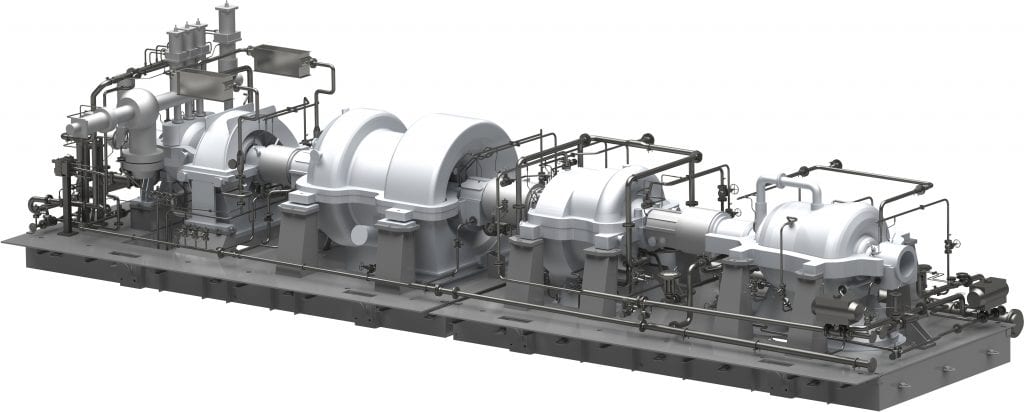
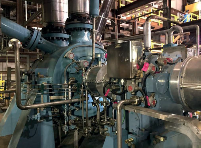
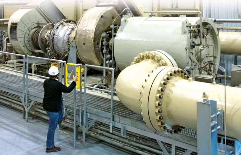
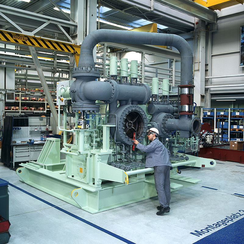
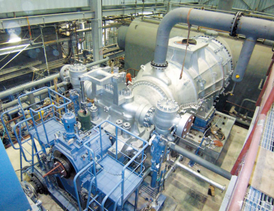
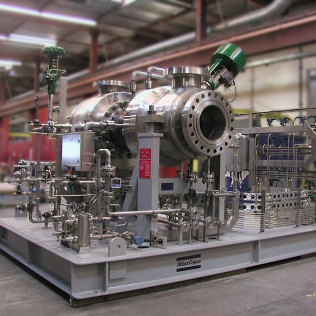
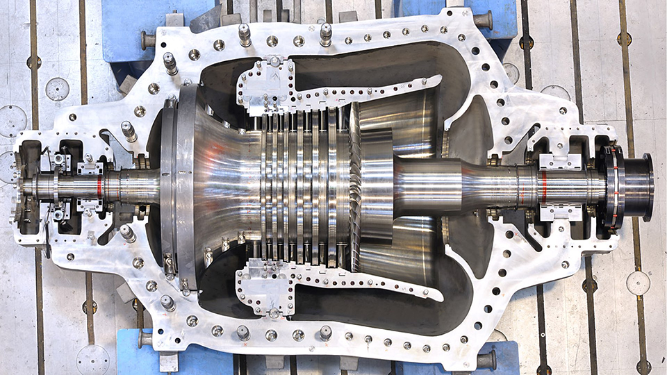
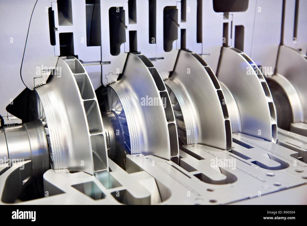
CENTRIFUGAL COMPRESSORS
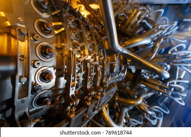
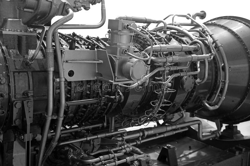
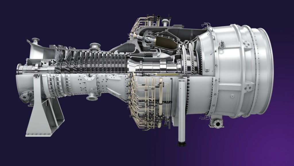
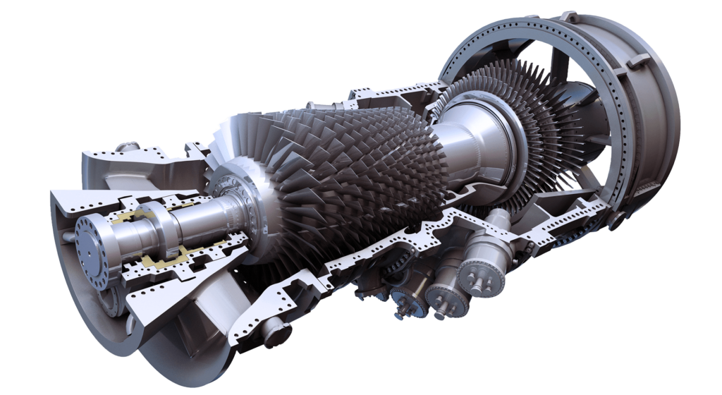
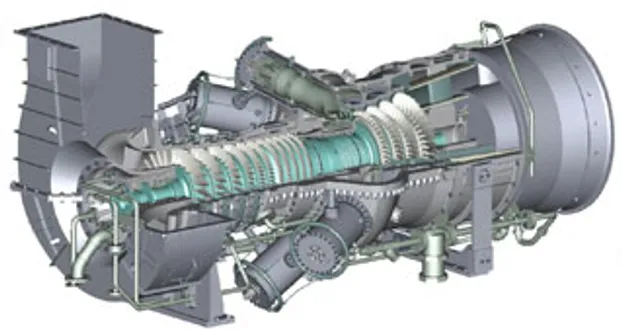
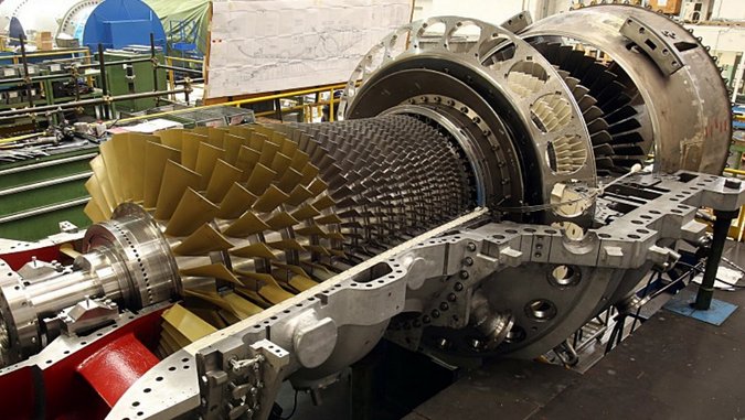
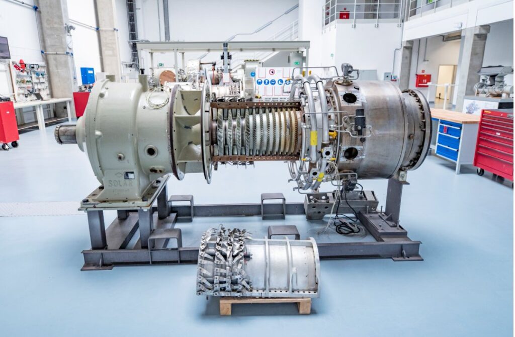
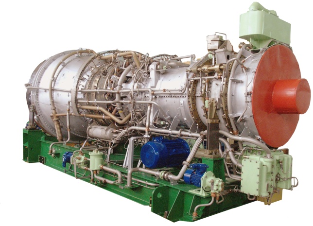
GAS TURBINES
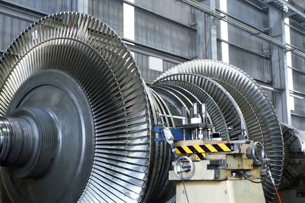
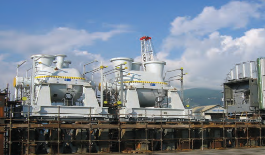
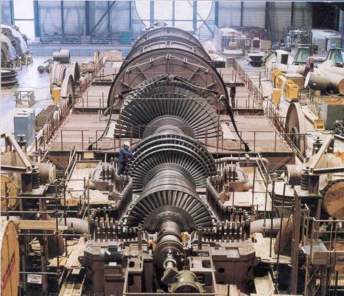
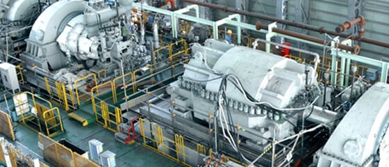
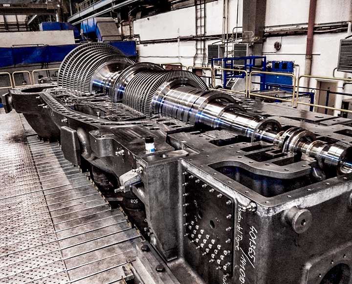
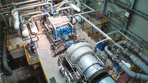
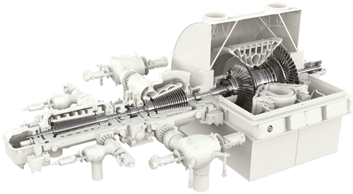
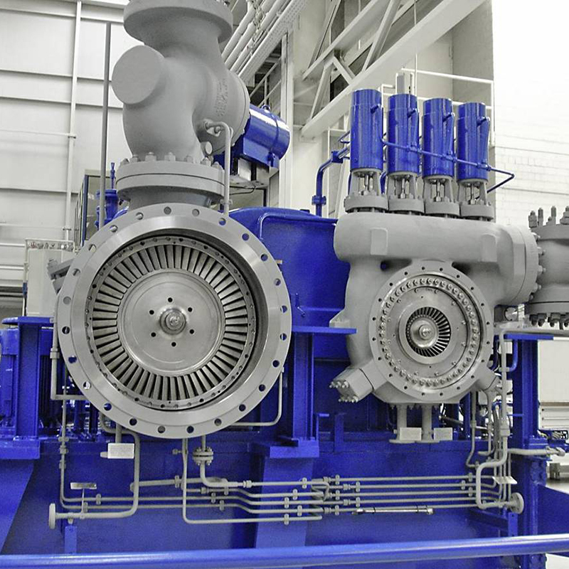
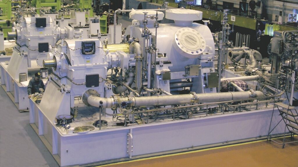
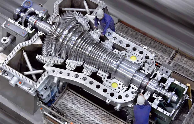
SPECIAL STEAM TURBINES
Frequency response functions (FRFs), phase, coherence, and modal analysis are important techniques in the study and analysis of turbomachinery. They help in understanding the dynamic behavior, performance characteristics, and structural integrity of the equipment. Here’s an explanation of these concepts and their applicability to turbomachinery:
Frequency Response Functions (FRFs):
- FRFs describe the system’s response to different frequencies of excitation. They provide information about the amplitude and phase relationship between input and output signals in the frequency domain.
- In turbomachinery analysis, FRFs are used to characterize the dynamic response of the equipment to external excitations, such as unbalance, fluid forces, or rotor-stator interactions.
- FRFs can be obtained through experimental modal analysis or operational vibration measurements. They help identify the natural frequencies, resonances, damping properties, and amplification or attenuation of vibrations at different frequencies.
- Analyzing the FRFs helps in identifying potential issues related to resonance, critical speeds, or operating conditions that can lead to excessive vibrations, instability, or failure in turbomachinery.
Phase:
- Phase refers to the time shift or delay between the input and output signals of a system. It represents the relationship between the timing of the input excitation and the corresponding response of the system.
- In turbomachinery analysis, phase measurements are used to determine the timing or synchronicity of different vibration signals. They can reveal phase differences between measurement points, providing insights into the relative motions or vibrations between components.
- Phase analysis helps in identifying problems such as misalignment, unbalance, or structural issues that can cause phase differences between measurement points. It aids in pinpointing the location and nature of vibration sources within the turbomachinery.
Coherence:
- Coherence is a statistical measure that quantifies the correlation between two signals at different frequencies. It indicates the degree of linear relationship or coupling between the input and output signals.
- In turbomachinery analysis, coherence is used to assess the consistency and reliability of measured signals. It helps differentiate between true system responses and external noise or measurement artifacts.
- High coherence values indicate a strong correlation between the input and output signals, suggesting reliable measurements. Low coherence values suggest that the measured signals are less correlated, potentially due to noise or measurement errors.
- Coherence analysis aids in the identification of measurement locations with poor signal quality or sources of interference, ensuring accurate and trustworthy data for further analysis and diagnosis.
Modal Analysis:
- Modal analysis is a technique used to determine the natural frequencies, mode shapes, and damping characteristics of a structure or system.
- In turbomachinery, modal analysis helps in understanding the dynamic behavior and structural integrity by identifying the vibration modes and their corresponding frequencies.
- Modal analysis is typically conducted through experimental testing or numerical simulations. It provides insights into the equipment’s response to excitations, critical speeds, mode localization, and potential resonance conditions.
- By performing modal analysis, engineers can assess the vibration characteristics, identify mode shapes that may lead to structural issues, and make design modifications or operational adjustments to avoid critical failures.
Applicability to Turbomachinery:
- FRFs, phase, coherence, and modal analysis are highly applicable to turbomachinery analysis.
- They help identify critical frequencies, resonances, and potential vibration issues that can affect the reliability, availability, safety, efficiency, and performance of turbomachinery.
- By utilizing these techniques, experts can diagnose and troubleshoot vibration problems, optimize design parameters, improve performance, and ensure the structural integrity of turbomachinery components.
- These analyses are commonly employed during the design, commissioning, maintenance, and operation of turbomachinery, enabling proactive measures to prevent critical failures, optimize performance, and extend the operational life of the equipment.
In summary, frequency response functions, phase, coherence, and modal analysis are valuable tools for understanding and assessing the dynamic behavior, performance characteristics, and structural integrity of turbomachinery. Their applications range from design optimization and commissioning to maintenance and troubleshooting in various industries, including power generation, oil and gas, and other turbomachinery-driven sectors.
ADVANTAGES & DISADVANTAGES TO GET DIAGNOSTICS WITH FREQUENCY RESPONSE FUNCTIONS (FRF), PHASE, COHERENCE AND MODAL ANALYSIS
Advantages:
Early Detection of Issues:
- Diagnostic tools enable early detection of potential problems in turbomachinery. By analyzing FRFs, phase, coherence, and modal characteristics, these tools can identify emerging issues before they escalate into critical failures or safety hazards.
- Early detection allows for proactive maintenance and repair, minimizing downtime and reducing the likelihood of expensive repairs or equipment replacement.
Improved Reliability and Availability:
- By providing insights into the dynamic behavior of turbomachinery, diagnostic tools help optimize equipment performance and ensure its reliability.
- Regular analysis of FRFs, phase, coherence, and modal characteristics helps identify potential sources of vibration, unbalance, misalignment, or resonance, enabling timely corrective actions to prevent failures and maximize equipment availability.
Enhanced Safety:
- Diagnostic tools play a crucial role in ensuring the safety of turbomachinery systems. By monitoring and analyzing vibrations, phase relationships, and coherence, these tools can identify potential safety risks, such as excessive vibrations, fatigue or stress on components, or structural integrity issues.
- Early detection of safety risks allows for preventive measures and corrective actions, mitigating the potential for accidents, equipment damage, or personal injuries.
Optimal Performance and Efficiency:
- Diagnostic tools aid in optimizing the operational performance and efficiency of turbomachinery. By analyzing FRFs, phase, coherence, and modal characteristics, engineers can identify factors impacting performance, such as unbalance, misalignment, or inefficient component operation.
- By addressing these factors, diagnostic tools facilitate adjustments and improvements that optimize the performance, energy efficiency, and operational costs of turbomachinery.
Targeted Maintenance and Repair:
- Diagnostic tools provide valuable insights into the root causes of issues, enabling targeted maintenance and repair actions. By understanding the specific vibration modes, phase relationships, and coherence patterns, maintenance activities can be focused on the areas that require attention, reducing unnecessary downtime and costs.
Disadvantages:
Initial Investment and Implementation:
- Implementing diagnostic tools may require an initial investment in hardware, software, and training. This can include the cost of acquiring the tools, installing sensors, and training personnel to effectively use and interpret the diagnostic data.
- Implementation may also involve challenges in integrating the tools with existing plant infrastructure or control systems.
Expertise and Interpretation:
- Proper interpretation of diagnostic results requires expertise in vibration analysis, structural dynamics, and turbomachinery behavior. Skilled personnel are needed to accurately analyze the data and make informed decisions based on the diagnostic outputs.
- Developing and maintaining the necessary expertise within an organization can be time-consuming and may require ongoing training and collaboration with specialists.
Data Acquisition Challenges:
- Obtaining accurate and comprehensive data for analysis can be challenging, particularly in existing turbomachinery systems. Retrofitting sensors or obtaining access to critical components may present difficulties, limiting the availability and quality of data for analysis.
Limitations of Analysis Techniques:
- Each diagnostic tool has its limitations and assumptions. FRFs, phase, coherence, and modal analysis techniques may have constraints related to accuracy, validity of assumptions, and specific applicability to certain turbomachinery configurations or operating conditions.
- Care must be taken to select and apply the appropriate analysis techniques for the specific turbomachinery system and desired diagnostic goals.
While diagnostic tools provide significant advantages in improving reliability, safety, and operational performance, addressing the associated disadvantages is crucial. By carefully considering the initial investment, expertise requirements, data acquisition challenges, and limitations of the analysis techniques, organizations can effectively leverage these tools to enhance their turbomachinery systems while ensuring the reliability, safety, and performance of centrifugal compressors, gas turbines, and special steam turbines.
WHY, WHEN, WHERE, WHAT, WHICH AND HOW TO GET DIAGNOSTICS WITH FREQUENCY RESPONSE FUNCTIONS (FRF), PHASE , COHERENCE AND MODAL ANALYSIS
Why use Diagnostic Tools:
- Diagnostic tools provide valuable insights into the dynamic behavior and performance characteristics of turbomachinery.
- By analyzing FRFs, phase, coherence, and modal characteristics, these tools can detect and address potential issues early, improving reliability, safety, and operational performance.
- Diagnostic tools enable proactive maintenance and repair, minimizing downtime, reducing the likelihood of critical failures, and optimizing the performance of turbomachinery.
Where to Apply Diagnostic Tools:
- Diagnostic tools can be applied to various turbomachinery systems, including centrifugal compressors, gas turbines, and special steam turbines.
- They are applicable in power generation plants, oil and gas industries, and other sectors where turbomachinery is utilized.
When to Use Diagnostic Tools:
- Diagnostic tools should be used throughout the lifecycle of turbomachinery, including during design, manufacturing, commissioning, operation, and maintenance stages.
- Regular monitoring and analysis with these tools help identify potential issues, assess the health of turbomachinery, and make informed decisions for maintenance and optimization.
What Diagnostic Tools Provide:
- FRFs provide information about the response of turbomachinery to different frequencies, including natural frequencies, resonances, and amplification or attenuation of vibrations.
- Phase analysis reveals the time shift or delay between input and output signals, aiding in identifying the relative motions or vibrations between components.
- Coherence analysis assesses the correlation between signals, ensuring reliable measurements.
- Modal analysis determines the natural frequencies, mode shapes, and damping characteristics of the turbomachinery, assisting in assessing the structural integrity and vibration behavior.
Which Tools to Use:
- Frequency response functions, phase and coherence analysis, and modal analysis are widely used diagnostic tools for turbomachinery.
- Specific techniques and tools within these categories may vary based on the desired analysis goals and the availability of resources.
How to Apply Diagnostic Tools:
- Implement a comprehensive condition monitoring program that includes regular data collection using appropriate sensors and instrumentation.
- Conduct data analysis using specialized software or algorithms to generate FRFs, analyze phase relationships, assess coherence, and perform modal analysis.
- Interpret the diagnostic results, compare them with established benchmarks or standards, and make informed decisions regarding maintenance, repairs, or operational adjustments.
- Collaborate with experts in vibration analysis, structural dynamics, and turbomachinery behavior to ensure accurate interpretation of diagnostic data and optimal utilization of the tools.
- Continuously improve the diagnostic capabilities by investing in training, staying updated with advancements in the field, and incorporating feedback from diagnostic results into the maintenance and optimization strategies.
By leveraging diagnostic tools effectively in turbomachinery applications, organizations can improve the reliability, safety, and operational performance of centrifugal compressors, gas turbines, and special steam turbines. These tools provide valuable insights into the behavior of turbomachinery, enable early issue detection, and inform decision-making for maintenance, repairs, and operational adjustments.
PROCEDURES, ACTIONS, STUDIES, ANALYSIS, MITIGATIONS AND RECOMMENDATIONS TO GET DIAGNOSTICS IN FRF, PHASE, COHERENCE AND MODAL ANALYSIS
Establish a Diagnostic Program:
- Define a comprehensive diagnostic program that outlines the objectives, scope, and implementation strategy for using diagnostic tools in turbomachinery analysis.
- Identify the key turbomachinery systems, components, and parameters of interest for diagnostics.
- Allocate resources, including personnel, time, and budget, to support the diagnostic program.
Data Acquisition and Instrumentation:
- Identify appropriate sensors and measurement techniques to capture relevant data, such as vibrations, temperatures, pressures, and other operating parameters.
- Install sensors at critical locations on the turbomachinery to obtain accurate and representative measurements.
- Ensure proper calibration and maintenance of the measurement instruments to ensure data integrity.
Data Collection and Management:
- Develop a data collection plan to capture the necessary data for analysis.
- Establish data management protocols to ensure proper organization, storage, and accessibility of the collected data.
- Implement a data acquisition system to automate data collection where possible.
Analysis Techniques:
- Utilize software tools and algorithms to analyze the collected data and generate frequency response functions (FRFs), phase relationships, coherence values, and modal characteristics.
- Apply advanced signal processing and statistical techniques to identify patterns, trends, anomalies, and potential issues in the data.
- Perform advanced analysis techniques, such as time-frequency analysis, order analysis, or operating deflection shape analysis, to gain deeper insights into the turbomachinery behavior.
Root Cause Analysis and Troubleshooting:
- Use the diagnostic results to conduct root cause analysis of any identified issues or anomalies.
- Perform troubleshooting activities to identify the underlying causes of performance degradation, vibration excitation, or safety concerns.
- Utilize the insights from diagnostic tools to guide targeted maintenance, repairs, or adjustments to address the identified issues.
Mitigations and Recommendations:
- Based on the findings from the analysis, develop mitigation strategies to address identified issues and improve the reliability, safety, and operational performance of the turbomachinery.
- Implement corrective actions, such as balancing, alignment, bearing replacements, or design modifications, to address structural, mechanical, or operational issues.
- Develop and document recommendations for maintenance practices, operational procedures, or design improvements to prevent future occurrences of identified issues.
Continuous Improvement and Monitoring:
- Establish a feedback loop to incorporate lessons learned from the diagnostic activities into the maintenance and operational strategies.
- Continuously monitor and evaluate the effectiveness of the diagnostic program and adjust the procedures, analysis techniques, or instrumentation as needed.
- Stay up-to-date with advancements in diagnostic tools, analysis methods, and industry best practices to continuously improve the diagnostic capabilities.
It is crucial to involve experienced personnel with expertise in vibration analysis, structural dynamics, and turbomachinery behavior to carry out these procedures effectively. Collaboration with manufacturers, industry experts, and specialized diagnostic service providers can also bring valuable insights and support to the diagnostic efforts.
By implementing these procedures, actions, studies, analysis techniques, mitigations, and recommendations, organizations can harness the potential of diagnostic tools to improve the reliability, safety, and operational performance of centrifugal compressors, gas turbines, and special steam turbines. Regular diagnostics and proactive maintenance based on the findings can help optimize the performance of turbomachinery and extend its operational life.