Alberto Mtz Llaurado

Consulting – FREQUENCY RESPONSE FUNCTIONS (RFR), PHASE, COHERENCE AND MODAL ANALYSIS IN TURBOMACHINERY

FREQUENCY RESPONSE FUNCTIONS (FRF), PHASE, COHERENCE AND MODAL ANALYSIS IN TURBOMACHINERY
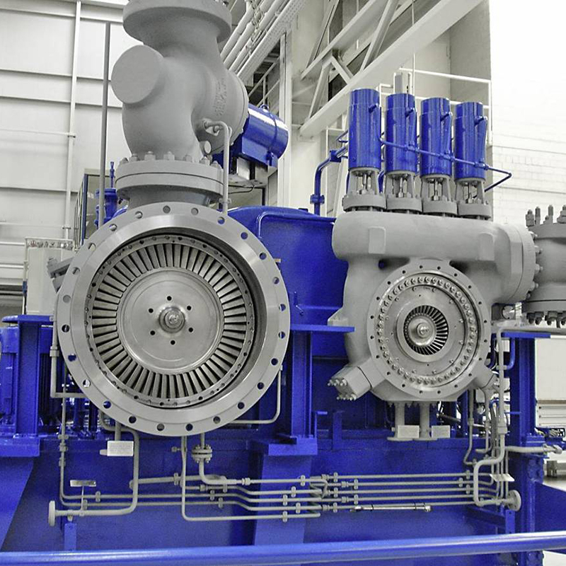
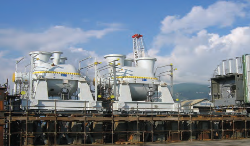
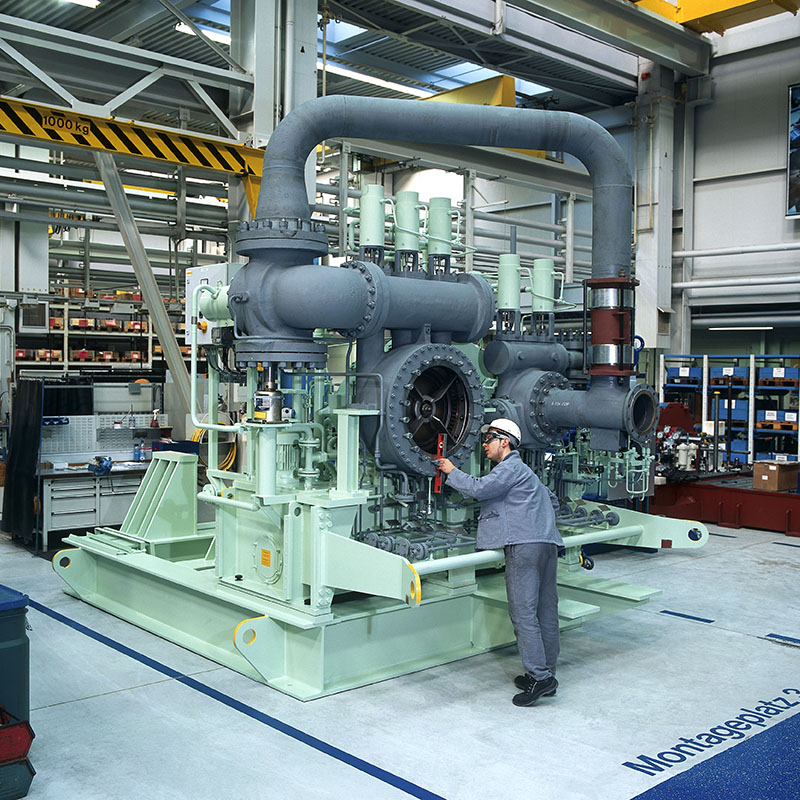
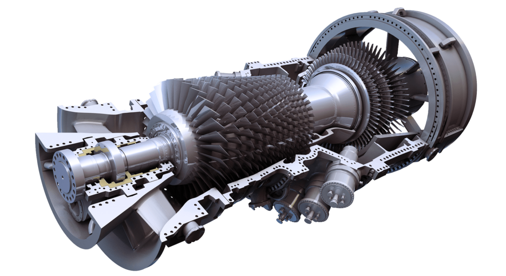
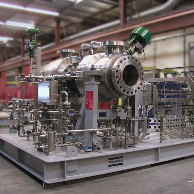
Courtesy by MAN
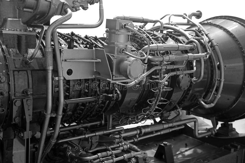
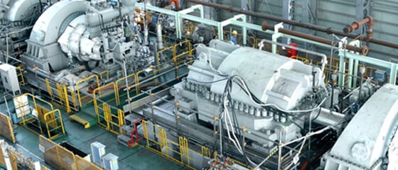
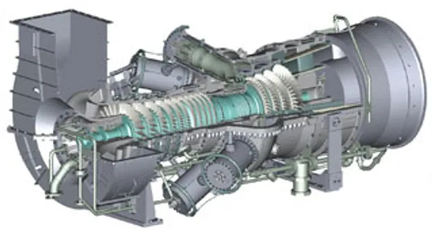
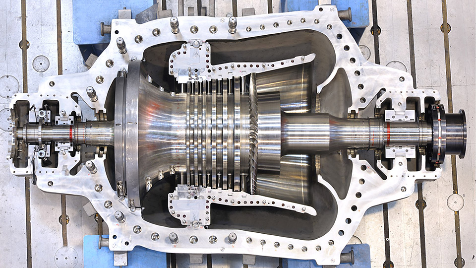
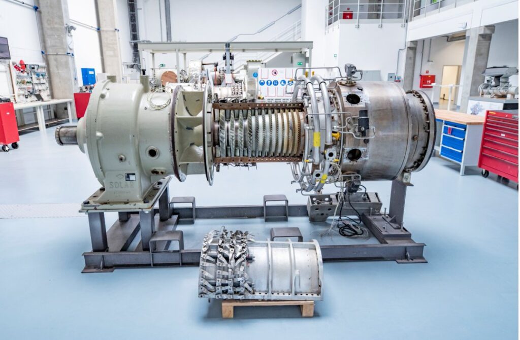
Courtesy by SOLAR TURBINES
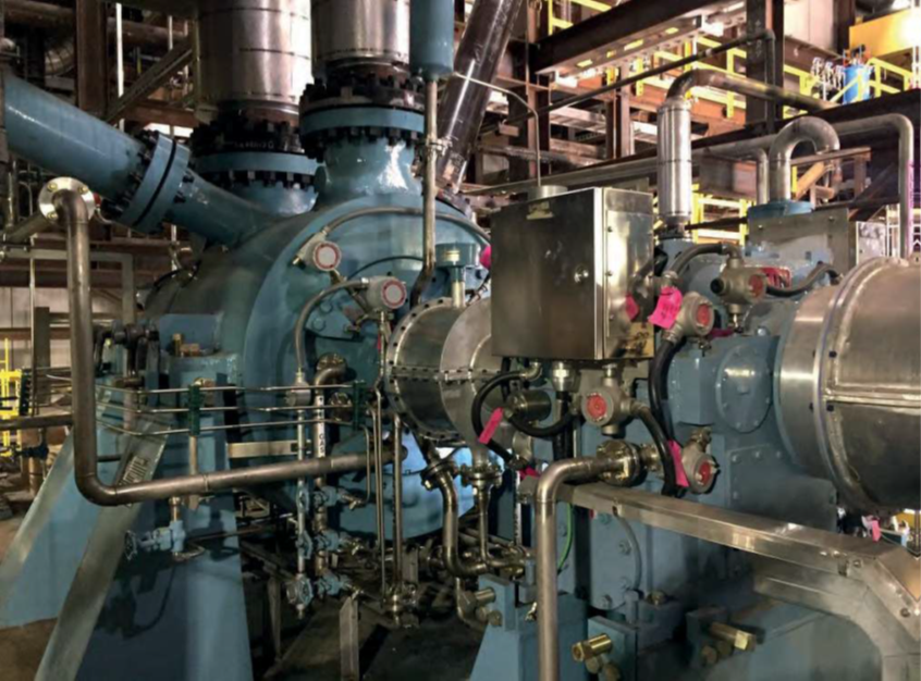
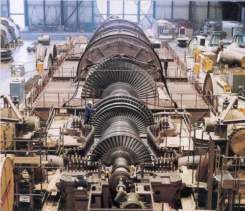
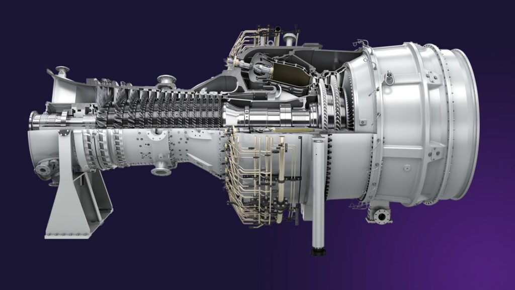
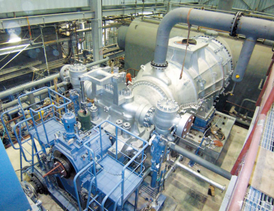
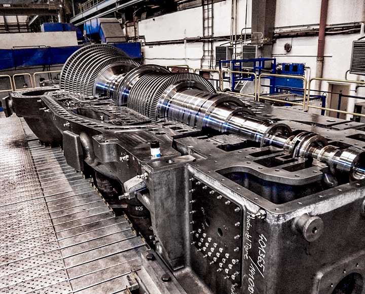
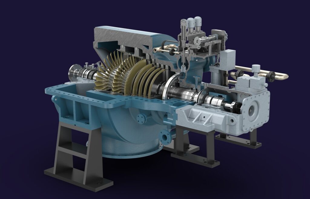
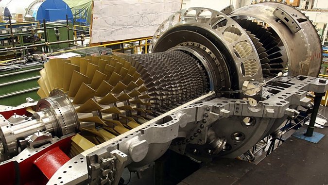
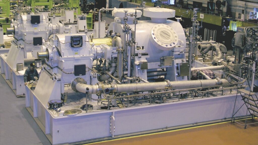
Courtesy by HOWDEN

CENTRIFUGAL COMPRESSORS

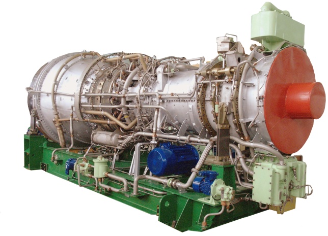
GAS TURBINES

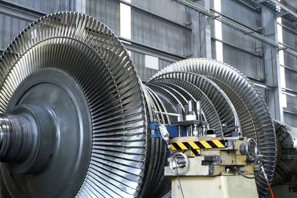
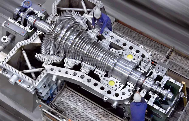
SPECIAL STEAM TURBINES

Frequency response functions (FRFs), phase, coherence, and modal analysis are important techniques in the study and analysis of turbomachinery. They help in understanding the dynamic behavior, performance characteristics, and structural integrity of the equipment. Here’s an explanation of these concepts and their applicability to turbomachinery:

  1. Frequency Response Functions (FRFs):

    • FRFs describe the system’s response to different frequencies of excitation. They provide information about the amplitude and phase relationship between input and output signals in the frequency domain.
    • In turbomachinery analysis, FRFs are used to characterize the dynamic response of the equipment to external excitations, such as unbalance, fluid forces, or rotor-stator interactions.
    • FRFs can be obtained through experimental modal analysis or operational vibration measurements. They help identify the natural frequencies, resonances, damping properties, and amplification or attenuation of vibrations at different frequencies.
    • Analyzing the FRFs helps in identifying potential issues related to resonance, critical speeds, or operating conditions that can lead to excessive vibrations, instability, or failure in turbomachinery.
  2. Phase:

    • Phase refers to the time shift or delay between the input and output signals of a system. It represents the relationship between the timing of the input excitation and the corresponding response of the system.
    • In turbomachinery analysis, phase measurements are used to determine the timing or synchronicity of different vibration signals. They can reveal phase differences between measurement points, providing insights into the relative motions or vibrations between components.
    • Phase analysis helps in identifying problems such as misalignment, unbalance, or structural issues that can cause phase differences between measurement points. It aids in pinpointing the location and nature of vibration sources within the turbomachinery.
  3. Coherence:

    • Coherence is a statistical measure that quantifies the correlation between two signals at different frequencies. It indicates the degree of linear relationship or coupling between the input and output signals.
    • In turbomachinery analysis, coherence is used to assess the consistency and reliability of measured signals. It helps differentiate between true system responses and external noise or measurement artifacts.
    • High coherence values indicate a strong correlation between the input and output signals, suggesting reliable measurements. Low coherence values suggest that the measured signals are less correlated, potentially due to noise or measurement errors.
    • Coherence analysis aids in the identification of measurement locations with poor signal quality or sources of interference, ensuring accurate and trustworthy data for further analysis and diagnosis.
  4. Modal Analysis:

    • Modal analysis is a technique used to determine the natural frequencies, mode shapes, and damping characteristics of a structure or system.
    • In turbomachinery, modal analysis helps in understanding the dynamic behavior and structural integrity by identifying the vibration modes and their corresponding frequencies.
    • Modal analysis is typically conducted through experimental testing or numerical simulations. It provides insights into the equipment’s response to excitations, critical speeds, mode localization, and potential resonance conditions.
    • By performing modal analysis, engineers can assess the vibration characteristics, identify mode shapes that may lead to structural issues, and make design modifications or operational adjustments to avoid critical failures.

Applicability to Turbomachinery:

  • FRFs, phase, coherence, and modal analysis are highly applicable to turbomachinery analysis.
  • They help identify critical frequencies, resonances, and potential vibration issues that can affect the reliability, availability, safety, efficiency, and performance of turbomachinery.
  • By utilizing these techniques, experts can diagnose and troubleshoot vibration problems, optimize design parameters, improve performance, and ensure the structural integrity of turbomachinery components.
  • These analyses are commonly employed during the design, commissioning, maintenance, and operation of turbomachinery, enabling proactive measures to prevent critical failures, optimize performance, and extend the operational life of the equipment.

In summary, frequency response functions, phase, coherence, and modal analysis are valuable tools for understanding and assessing the dynamic behavior, performance characteristics, and structural integrity of turbomachinery. Their applications range from design optimization and commissioning to maintenance and troubleshooting in various industries, including power generation, oil and gas, and other turbomachinery-driven sectors.

ADVANTAGES & DISADVANTAGES TO GET DIAGNOSTICS WITH FREQUENCY RESPONSE FUNCTIONS (FRF), PHASE, COHERENCE AND MODAL ANALYSIS

Advantages:

  1. Early Detection of Issues:

    • Diagnostic tools enable early detection of potential problems in turbomachinery. By analyzing FRFs, phase, coherence, and modal characteristics, these tools can identify emerging issues before they escalate into critical failures or safety hazards.
    • Early detection allows for proactive maintenance and repair, minimizing downtime and reducing the likelihood of expensive repairs or equipment replacement.
  2. Improved Reliability and Availability:

    • By providing insights into the dynamic behavior of turbomachinery, diagnostic tools help optimize equipment performance and ensure its reliability.
    • Regular analysis of FRFs, phase, coherence, and modal characteristics helps identify potential sources of vibration, unbalance, misalignment, or resonance, enabling timely corrective actions to prevent failures and maximize equipment availability.
  3. Enhanced Safety:

    • Diagnostic tools play a crucial role in ensuring the safety of turbomachinery systems. By monitoring and analyzing vibrations, phase relationships, and coherence, these tools can identify potential safety risks, such as excessive vibrations, fatigue or stress on components, or structural integrity issues.
    • Early detection of safety risks allows for preventive measures and corrective actions, mitigating the potential for accidents, equipment damage, or personal injuries.
  4. Optimal Performance and Efficiency:

    • Diagnostic tools aid in optimizing the operational performance and efficiency of turbomachinery. By analyzing FRFs, phase, coherence, and modal characteristics, engineers can identify factors impacting performance, such as unbalance, misalignment, or inefficient component operation.
    • By addressing these factors, diagnostic tools facilitate adjustments and improvements that optimize the performance, energy efficiency, and operational costs of turbomachinery.
  5. Targeted Maintenance and Repair:

    • Diagnostic tools provide valuable insights into the root causes of issues, enabling targeted maintenance and repair actions. By understanding the specific vibration modes, phase relationships, and coherence patterns, maintenance activities can be focused on the areas that require attention, reducing unnecessary downtime and costs.

Disadvantages:

  1. Initial Investment and Implementation:

    • Implementing diagnostic tools may require an initial investment in hardware, software, and training. This can include the cost of acquiring the tools, installing sensors, and training personnel to effectively use and interpret the diagnostic data.
    • Implementation may also involve challenges in integrating the tools with existing plant infrastructure or control systems.
  2. Expertise and Interpretation:

    • Proper interpretation of diagnostic results requires expertise in vibration analysis, structural dynamics, and turbomachinery behavior. Skilled personnel are needed to accurately analyze the data and make informed decisions based on the diagnostic outputs.
    • Developing and maintaining the necessary expertise within an organization can be time-consuming and may require ongoing training and collaboration with specialists.
  3. Data Acquisition Challenges:

    • Obtaining accurate and comprehensive data for analysis can be challenging, particularly in existing turbomachinery systems. Retrofitting sensors or obtaining access to critical components may present difficulties, limiting the availability and quality of data for analysis.
  4. Limitations of Analysis Techniques:

    • Each diagnostic tool has its limitations and assumptions. FRFs, phase, coherence, and modal analysis techniques may have constraints related to accuracy, validity of assumptions, and specific applicability to certain turbomachinery configurations or operating conditions.
    • Care must be taken to select and apply the appropriate analysis techniques for the specific turbomachinery system and desired diagnostic goals.

While diagnostic tools provide significant advantages in improving reliability, safety, and operational performance, addressing the associated disadvantages is crucial. By carefully considering the initial investment, expertise requirements, data acquisition challenges, and limitations of the analysis techniques, organizations can effectively leverage these tools to enhance their turbomachinery systems while ensuring the reliability, safety, and performance of centrifugal compressors, gas turbines, and special steam turbines.

Courtesy by SIEMENS
Courtesy by ZORYA
Courtesy by MAN

WHY, WHEN, WHERE, WHAT, WHICH AND HOW TO GET DIAGNOSTICS WITH FREQUENCY RESPONSE FUNCTIONS (FRF), PHASE , COHERENCE AND MODAL ANALYSIS

  1. Why use Diagnostic Tools:

    • Diagnostic tools provide valuable insights into the dynamic behavior and performance characteristics of turbomachinery.
    • By analyzing FRFs, phase, coherence, and modal characteristics, these tools can detect and address potential issues early, improving reliability, safety, and operational performance.
    • Diagnostic tools enable proactive maintenance and repair, minimizing downtime, reducing the likelihood of critical failures, and optimizing the performance of turbomachinery.
  2. Where to Apply Diagnostic Tools:

    • Diagnostic tools can be applied to various turbomachinery systems, including centrifugal compressors, gas turbines, and special steam turbines.
    • They are applicable in power generation plants, oil and gas industries, and other sectors where turbomachinery is utilized.
  3. When to Use Diagnostic Tools:

    • Diagnostic tools should be used throughout the lifecycle of turbomachinery, including during design, manufacturing, commissioning, operation, and maintenance stages.
    • Regular monitoring and analysis with these tools help identify potential issues, assess the health of turbomachinery, and make informed decisions for maintenance and optimization.
  4. What Diagnostic Tools Provide:

    • FRFs provide information about the response of turbomachinery to different frequencies, including natural frequencies, resonances, and amplification or attenuation of vibrations.
    • Phase analysis reveals the time shift or delay between input and output signals, aiding in identifying the relative motions or vibrations between components.
    • Coherence analysis assesses the correlation between signals, ensuring reliable measurements.
    • Modal analysis determines the natural frequencies, mode shapes, and damping characteristics of the turbomachinery, assisting in assessing the structural integrity and vibration behavior.
  5. Which Tools to Use:

    • Frequency response functions, phase and coherence analysis, and modal analysis are widely used diagnostic tools for turbomachinery.
    • Specific techniques and tools within these categories may vary based on the desired analysis goals and the availability of resources.
  6. How to Apply Diagnostic Tools:

    • Implement a comprehensive condition monitoring program that includes regular data collection using appropriate sensors and instrumentation.
    • Conduct data analysis using specialized software or algorithms to generate FRFs, analyze phase relationships, assess coherence, and perform modal analysis.
    • Interpret the diagnostic results, compare them with established benchmarks or standards, and make informed decisions regarding maintenance, repairs, or operational adjustments.
    • Collaborate with experts in vibration analysis, structural dynamics, and turbomachinery behavior to ensure accurate interpretation of diagnostic data and optimal utilization of the tools.
    • Continuously improve the diagnostic capabilities by investing in training, staying updated with advancements in the field, and incorporating feedback from diagnostic results into the maintenance and optimization strategies.

By leveraging diagnostic tools effectively in turbomachinery applications, organizations can improve the reliability, safety, and operational performance of centrifugal compressors, gas turbines, and special steam turbines. These tools provide valuable insights into the behavior of turbomachinery, enable early issue detection, and inform decision-making for maintenance, repairs, and operational adjustments.

PROCEDURES, ACTIONS, STUDIES, ANALYSIS, MITIGATIONS AND RECOMMENDATIONS TO GET DIAGNOSTICS IN FRF, PHASE, COHERENCE AND MODAL ANALYSIS

  1. Establish a Diagnostic Program:

    • Define a comprehensive diagnostic program that outlines the objectives, scope, and implementation strategy for using diagnostic tools in turbomachinery analysis.
    • Identify the key turbomachinery systems, components, and parameters of interest for diagnostics.
    • Allocate resources, including personnel, time, and budget, to support the diagnostic program.
  2. Data Acquisition and Instrumentation:

    • Identify appropriate sensors and measurement techniques to capture relevant data, such as vibrations, temperatures, pressures, and other operating parameters.
    • Install sensors at critical locations on the turbomachinery to obtain accurate and representative measurements.
    • Ensure proper calibration and maintenance of the measurement instruments to ensure data integrity.
  3. Data Collection and Management:

    • Develop a data collection plan to capture the necessary data for analysis.
    • Establish data management protocols to ensure proper organization, storage, and accessibility of the collected data.
    • Implement a data acquisition system to automate data collection where possible.
  4. Analysis Techniques:

    • Utilize software tools and algorithms to analyze the collected data and generate frequency response functions (FRFs), phase relationships, coherence values, and modal characteristics.
    • Apply advanced signal processing and statistical techniques to identify patterns, trends, anomalies, and potential issues in the data.
    • Perform advanced analysis techniques, such as time-frequency analysis, order analysis, or operating deflection shape analysis, to gain deeper insights into the turbomachinery behavior.
  5. Root Cause Analysis and Troubleshooting:

    • Use the diagnostic results to conduct root cause analysis of any identified issues or anomalies.
    • Perform troubleshooting activities to identify the underlying causes of performance degradation, vibration excitation, or safety concerns.
    • Utilize the insights from diagnostic tools to guide targeted maintenance, repairs, or adjustments to address the identified issues.
  6. Mitigations and Recommendations:

    • Based on the findings from the analysis, develop mitigation strategies to address identified issues and improve the reliability, safety, and operational performance of the turbomachinery.
    • Implement corrective actions, such as balancing, alignment, bearing replacements, or design modifications, to address structural, mechanical, or operational issues.
    • Develop and document recommendations for maintenance practices, operational procedures, or design improvements to prevent future occurrences of identified issues.
  7. Continuous Improvement and Monitoring:

    • Establish a feedback loop to incorporate lessons learned from the diagnostic activities into the maintenance and operational strategies.
    • Continuously monitor and evaluate the effectiveness of the diagnostic program and adjust the procedures, analysis techniques, or instrumentation as needed.
    • Stay up-to-date with advancements in diagnostic tools, analysis methods, and industry best practices to continuously improve the diagnostic capabilities.

It is crucial to involve experienced personnel with expertise in vibration analysis, structural dynamics, and turbomachinery behavior to carry out these procedures effectively. Collaboration with manufacturers, industry experts, and specialized diagnostic service providers can also bring valuable insights and support to the diagnostic efforts.

By implementing these procedures, actions, studies, analysis techniques, mitigations, and recommendations, organizations can harness the potential of diagnostic tools to improve the reliability, safety, and operational performance of centrifugal compressors, gas turbines, and special steam turbines. Regular diagnostics and proactive maintenance based on the findings can help optimize the performance of turbomachinery and extend its operational life.

Consulting – FREQUENCY RESPONSE FUNCTIONS (RFR), PHASE, COHERENCE AND MODAL ANALYSIS IN TURBOMACHINERY Leer más »
Consulting – DIAGNOSTIC TOOLS TO AVOID FAILURES IN TURBOMACHINERY

DIAGNOSTIC TOOLS TO AVOID FAILURES IN TURBOMACHINERY

CENTRIFUGAL COMPRESSORS

GAS TURBINES

SPECIAL STEAM TURBINES

WHY USE DIAGNOSTIC TOOLS TO AVOID FAILURES IN TURBOMACHINERY

Here’s why these tools are important:

  1. Early Detection of Issues:

    • Vibration analyzers allow for real-time monitoring and analysis of vibrations in turbomachinery. By detecting abnormal vibration patterns, such as those caused by imbalance, misalignment, or mechanical faults, potential issues can be identified early, enabling timely maintenance or corrective actions to prevent critical failures.
    • Operational performance software monitors key parameters such as temperatures, pressures, flow rates, and efficiency. Deviations from normal operating conditions can indicate potential issues or inefficiencies, enabling operators to take corrective measures before they escalate into critical failures.
    • Thermodynamic studies analyze the behavior of turbomachinery in terms of efficiency, temperature differentials, and energy transfer. These studies provide insights into potential performance degradation or abnormalities, facilitating proactive maintenance or operational adjustments.
  2. Reliability and Availability Improvement:

    • Diagnostic tools enable proactive maintenance and condition monitoring, enhancing the reliability and availability of turbomachinery. Early detection of potential failures or deviations from normal operation allows for scheduled maintenance and repairs, reducing the risk of unscheduled shutdowns and improving overall reliability.
    • By identifying and addressing potential issues early, operators can mitigate safety risks associated with critical failures, protecting personnel and equipment.
  3. Efficiency and Performance Optimization:

    • Diagnostic tools and simulations provide insights into the performance of turbomachinery, enabling operators to optimize efficiency and performance. By analyzing vibration patterns, operational data, and thermodynamic behavior, operators can make informed decisions regarding adjustments, maintenance actions, or operational strategies to improve efficiency, reliability, and overall performance.
  4. Safety Enhancement:

    • Proactive maintenance and condition monitoring through diagnostic tools help prevent critical failures that can pose safety hazards. By identifying and mitigating potential issues early, the risk of catastrophic events or accidents caused by turbomachinery failures is significantly reduced.
  5. Cost Reduction:

    • The use of diagnostic tools helps minimize unscheduled downtime, costly repairs, or replacements due to critical failures. Proactive maintenance based on diagnostic data enables efficient resource allocation, as maintenance activities can be planned in advance, reducing emergency repairs and associated costs.
    • Optimization of performance through analysis and simulations leads to energy savings, improved efficiency, and optimized operational strategies, resulting in reduced operational costs.
  6. Regulatory Compliance:

    • The use of diagnostic tools and adherence to recommended maintenance practices can help meet regulatory requirements for safety, reliability, and environmental standards in the power generation and oil and gas industries.

By using diagnostic tools based on vibration analyzers, operational performance software, thermodynamic studies, or mathematical models, industries can detect issues early, enhance reliability and availability, optimize efficiency and performance, improve safety, reduce costs, and comply with regulatory standards. This proactive approach helps avoid critical failures or impacts in turbomachinery, ensuring the reliability, availability, safety, efficiency, and performance of existing and new plants in the power generation and oil and gas industries, while avoiding critical failures or unscheduled shutdowns.

WHERE, WHEN, WHAT, WHICH AND HOW TO USE DIAGNOSTIC TOOLS TO AVOID FAILURES IN TURBOMACHINERY

  1. Where to Use Diagnostic Tools:

    • Diagnostic tools should be used in power generation plants and oil and gas facilities that utilize turbomachinery such as centrifugal compressors, gas turbines, and special steam turbines.
    • These tools can be applied in various locations, including compressor or turbine rooms, control rooms, or monitoring centers, where the necessary sensors, software, and data analysis systems can be installed and managed.
  2. When to Use Diagnostic Tools:

    • Diagnostic tools should be used throughout the lifecycle of turbomachinery, including during the design, commissioning, operation, and maintenance stages.
    • Continuous monitoring and analysis are recommended during normal operating conditions, as well as during offset conditions, which involve non-standard or transient operations.
    • Regular data collection and analysis should be performed to establish baseline performance, identify deviations, and detect potential issues early.
  3. What Diagnostic Tools to Use:

    • Vibration analyzers are used to monitor and analyze the vibration levels and patterns of turbomachinery components, such as rotors, bearings, and blades, to identify abnormalities and potential failures.
    • Operational performance software allows for real-time monitoring and analysis of key operational parameters, such as temperatures, pressures, flow rates, and efficiency, to detect deviations from normal operating conditions.
    • Thermodynamic studies analyze the behavior of turbomachinery in terms of compression efficiency, temperature differentials, energy transfer, and fluid flow characteristics, providing insights into performance, efficiency, and potential issues.
    • Mathematical models, such as finite element analysis (FEA), computational fluid dynamics (CFD), and system simulation tools, are used to simulate and analyze the dynamic and thermodynamic behavior of turbomachinery, predicting critical frequencies, stresses, flow characteristics, and overall performance.
  4. Which Components and Parameters to Monitor:

    • Diagnostic tools should monitor critical components, such as rotors, bearings, blades, seals, valves, and casings, as well as important operational parameters, including temperatures, pressures, flow rates, and efficiency.
    • The specific components and parameters to monitor may vary based on the type of turbomachinery and its critical failure modes, as well as the design and operational characteristics of the plant.
  5. How to Use Diagnostic Tools:

    • Install appropriate sensors and instrumentation in strategic locations to capture relevant data from the turbomachinery components and operational parameters.
    • Utilize dedicated software or systems to collect, store, and analyze the data obtained from the diagnostic tools.
    • Regularly analyze the data to establish baselines, detect deviations, and identify potential issues or trends.
    • Interpret the diagnostic results with the help of experts and specialists in vibration analysis, thermodynamics, and mathematical modeling.
    • Take appropriate actions based on the analysis findings, including implementing maintenance or repair activities, adjusting operational parameters, or optimizing design features.

It’s important to note that the specific application of diagnostic tools may vary depending on the plant’s unique requirements, industry standards, and manufacturer recommendations. Engaging with industry experts, manufacturers, and consultants can provide valuable guidance on the selection, installation, and utilization of diagnostic tools for turbomachinery.

By using diagnostic tools effectively in the right locations, at the appropriate times, and for the relevant components and parameters, industries can obtain reliable analysis and simulations, enabling them to proactively avoid critical failures or impacts in turbomachinery. This approach ensures improved reliability, availability, safety, efficiency, and performance in both existing and new power generation plants and oil and gas facilities, while minimizing the risk of critical failures or unscheduled shutdowns.

LIMITATIONS IN ENGINEERING & DESIGN TO USE DIAGNOSTIC TOOLS TO AVOID FAILURES IN TURBOMACHINERY

Here are some key limitations:

  1. Complex Operating Conditions:

    • Turbomachinery, such as centrifugal compressors, gas turbines, and special steam turbines, operates under complex and varying conditions, including high temperatures, pressures, and rotational speeds. These conditions can pose challenges for accurate measurements, analysis, and simulation using diagnostic tools.
    • Extreme operating conditions may limit the availability or suitability of certain sensors, materials, or instrumentation required for effective data collection and analysis.
  2. Limited Accessibility and Space Constraints:

    • The design of turbomachinery often involves tight spaces, intricate geometries, and restricted access to critical components. This can make the installation of sensors, monitoring equipment, or diagnostic tools challenging or even impractical.
    • Limited space can also restrict the implementation of certain diagnostic tools, such as vibration analyzers or additional instrumentation, which may require modifications or compromises in the equipment design.
  3. Complex Dynamics and Fluid Mechanics:

    • The behavior of turbomachinery involves complex dynamics, including rotor dynamics, fluid-structure interactions, and unsteady fluid flows. These complexities can make it challenging to accurately model and predict the behavior of turbomachinery using mathematical models or simulations.
    • Capturing the full range of transient or off-design operating conditions and their impact on turbomachinery performance can be difficult, potentially limiting the accuracy and reliability of the analysis and simulations.
  4. Lack of Comprehensive Data:

    • Accurate diagnostic analysis and reliable simulations depend on the availability of comprehensive and accurate data. However, obtaining complete data sets during operation, especially for existing plants, can be challenging.
    • Limited or incomplete data, such as operating conditions, performance parameters, or historical records, may constrain the effectiveness of diagnostic tools, as they rely on accurate input data for calibration, validation, and accurate modeling.
  5. Expertise and Resources:

    • Effective utilization of diagnostic tools requires expertise in vibration analysis, thermodynamics, mathematical modeling, and simulation techniques. The availability of qualified personnel, time, and resources to interpret and apply the diagnostic results may be limited, potentially affecting the reliability and effectiveness of the analysis and simulations.
  6. Compatibility and Integration:

    • Integrating diagnostic tools into existing turbomachinery systems, control systems, or plant infrastructure may require compatibility with different communication protocols, data management systems, or software interfaces. These compatibility challenges can hinder the seamless integration and utilization of diagnostic tools in the existing plant setup.

It is important to acknowledge these limitations and consider them during the engineering and design phases. Collaboration between equipment manufacturers, industry experts, and researchers is crucial to addressing these limitations and advancing the capabilities of diagnostic tools.

Despite these limitations, the utilization of diagnostic tools can still provide valuable insights and contribute to the prevention of critical failures or impacts in turbomachinery. By considering these limitations and applying a holistic approach that combines diagnostic tools with other preventive measures, such as robust design practices, comprehensive maintenance programs, and expert consultation, industries can improve the reliability, availability, safety, efficiency, and performance of turbomachinery in power generation plants and the oil and gas industries while minimizing the risk of critical failures or unscheduled shutdowns.

PROCEDURES, ACTIONS, STUDIES, ANALYSIS, MITIGATIONS AND RECOMMENDATIONS TO USE DIAGNOSTIC TOOLS TO AVOID FAILURES IN TURBOMACHINERY

  1. Procedures and Actions:

    • Establish a comprehensive condition monitoring program that includes the use of vibration analyzers and operational performance software. This program should define the frequency of data collection, locations of sensors, and procedures for data analysis.
    • Develop and implement a proactive maintenance strategy based on the diagnostic data. This strategy should include regular inspection, lubrication, and replacement of critical components, as well as addressing any identified issues promptly.
    • Conduct regular thermodynamic studies to analyze the behavior of turbomachinery, evaluate performance metrics, and identify opportunities for optimization.
    • Utilize mathematical models, such as finite element analysis (FEA), computational fluid dynamics (CFD), and system simulation tools, to simulate and analyze the dynamic and thermodynamic behavior of turbomachinery for reliability assessments and performance optimizations.
  2. Studies and Analysis:

    • Conduct baseline studies to establish the normal operating conditions, vibration levels, and performance parameters of the turbomachinery. This provides a reference point for identifying deviations and abnormalities.
    • Perform comprehensive vibration analysis to identify potential issues such as imbalance, misalignment, mechanical faults, or resonance in critical components.
    • Utilize operational performance software to monitor key parameters such as temperatures, pressures, flow rates, and efficiency. Analyze the data to detect deviations from normal operating conditions.
    • Conduct thermodynamic studies to evaluate compression efficiency, temperature differentials, energy transfer, and fluid flow characteristics. Compare the results with design specifications and identify areas for improvement or optimization.
  3. Analysis and Mitigations:

    • Analyze the diagnostic data collected from the tools to identify trends, patterns, and anomalies that may indicate potential failures or impacts.
    • Implement a robust maintenance and repair program based on the diagnostic findings. Address identified issues promptly to prevent their progression into critical failures.
    • Optimize operational parameters, such as speed, load, and control settings, based on the insights gained from the analysis and simulations to maximize efficiency and minimize the likelihood of critical failures.
    • Incorporate design modifications, such as improved materials, damping mechanisms, or component geometries, based on the results of the analysis and simulations to mitigate resonance, improve reliability, and reduce the risk of critical failures.
    • Apply recommended operational and maintenance practices, such as proper lubrication, alignment, and valve maintenance, to ensure the reliability and availability of the turbomachinery.
  4. Recommendations:

    • Engage with experts in vibration analysis, thermodynamics, and mathematical modeling to interpret the diagnostic data, conduct detailed analyses, and provide recommendations for maintenance, design modifications, or operational improvements.
    • Foster collaboration and knowledge-sharing between industry professionals, manufacturers, and researchers to exchange best practices and experiences related to using diagnostic tools effectively in turbomachinery.
    • Regularly review and update industry standards and guidelines to incorporate the latest knowledge and advancements in diagnostic techniques and mitigation strategies for critical failures or impacts.

By following these procedures, taking appropriate actions, conducting studies and analysis, implementing mitigations, and considering recommendations, the power generation plants and oil and gas industries can effectively use diagnostic tools to prevent critical failures or impacts in turbomachinery. This proactive approach ensures improved reliability, availability, safety, efficiency, and performance of the turbomachinery in both existing and new plants while avoiding critical failures or unscheduled shutdowns.

Consulting – DIAGNOSTIC TOOLS TO AVOID FAILURES IN TURBOMACHINERY Leer más »

Consulting – IMPACTS BY STRUCTURAL RESONANCE – TURBOMACHINERY

IMPACTS BY STRUCTURAL RESONANCE - TURBOMACHINERY

Courtesy by SOLAR TURBINES
Courtesy by SIEMENS
Courtesy by HOWDEN

CENTRIFUGAL COMPRESSORS

GAS TURBINES

SPECIAL STEAM TURBINES

Structural resonance in turbomachinery, including centrifugal compressors, gas turbines, and steam turbines, can have critical impacts on the reliability, availability, safety, and performance of these machines in various industries such as oil, gas, and power generation. Let’s explore the effects of structural resonance in both normal and offset operating conditions.

  1. Reliability and Availability:

    • Structural resonance can lead to increased vibration levels in turbomachinery, which may result in accelerated wear and fatigue of components such as blades, rotors, and casings. This can reduce the reliability and availability of the machinery, leading to more frequent maintenance and downtime.
    • Resonance-induced vibrations can cause unexpected failures, resulting in unplanned shutdowns and disruptions in production. These disruptions can have significant financial implications for the plant operators.
  2. Safety:

    • Excessive vibrations caused by structural resonance can compromise the integrity of the turbomachinery and its supporting structures. This can lead to mechanical failures, such as blade or rotor fractures, which pose safety risks to personnel and nearby equipment.
    • Severe vibrations can also result in increased stresses on the machine’s foundation, leading to potential structural failures and risks to the overall plant safety.
  3. Performance:

    • Resonance-related vibrations can negatively impact the overall performance of turbomachinery. Increased vibration levels can cause a loss in efficiency by affecting the aerodynamic performance of compressor or turbine blades, resulting in reduced output and increased energy consumption.
    • Vibrations can also lead to changes in clearances and alignments, affecting the operating parameters of the machine, such as flow rates, pressure ratios, and temperature differentials. This can further impact the performance and efficiency of the turbomachinery.
  4. Existing and New Plants:

    • In existing plants, structural resonance issues may arise due to changes in operating conditions, degradation of components, or modifications in the surrounding infrastructure. Identifying and addressing these resonance concerns is crucial to maintaining the reliability and performance of the existing machinery.
    • For new plants, proper design and engineering practices are essential to mitigate the risks associated with structural resonance. Analytical tools such as finite element analysis, computational fluid dynamics, and modal analysis can be used during the design phase to identify potential resonance frequencies and optimize the machine’s dynamic behavior.

To manage the critical impacts of structural resonance in turbomachinery, industry practices include:

  • Conducting regular vibration monitoring and analysis to detect and diagnose resonance-related issues.
  • Implementing appropriate maintenance and inspection programs to identify and rectify potential resonance problems.
  • Employing advanced control systems and active damping techniques to suppress or mitigate vibrations.
  • Incorporating robust design practices and considering dynamic characteristics during the engineering phase.
  • Applying modifications or retrofits to address resonance concerns in existing machinery.

By proactively addressing structural resonance issues, industries can improve the reliability, availability, safety, and performance of turbomachinery in oil, gas, and power generation plants.

LIMITATIONS IN ENGINEERING & DESIGN FOR STRUCTURAL RESONANCE IN TURBOMACHINERY

While engineering and design practices play a crucial role in mitigating the critical impacts of structural resonance in turbomachinery, there are certain limitations that need to be considered. These limitations can affect the ability to completely eliminate resonance-related issues and address their impacts on reliability, availability, safety, and performance. Here are some key limitations:

  1. Complexity of Dynamic Behavior:

    • Turbomachinery systems are complex, involving multiple components, rotating parts, and fluid interactions. Understanding and predicting the dynamic behavior of these systems, including resonance frequencies and mode shapes, can be challenging.
    • The interaction between rotating and stationary components, such as blades, casings, and shafts, can introduce additional complexities in predicting and managing structural resonance. The dynamic behavior of these components may change under different operating conditions, making it difficult to accurately assess the resonance risks.
  2. Uncertainties in Operating Conditions:

    • Operating conditions, such as flow rates, temperatures, and pressure differentials, can vary in turbomachinery systems. These variations may lead to changes in the resonance characteristics and vibration levels.
    • Predicting the exact operating conditions that can lead to resonance can be challenging, particularly in dynamic environments or when the machinery is subjected to transient conditions. Uncertainties in these conditions make it difficult to develop comprehensive designs that completely eliminate resonance concerns.
  3. Limitations in Modeling and Analysis:

    • Modeling turbomachinery systems for resonance analysis requires simplifications and assumptions due to the complexity of the system. These simplifications can introduce uncertainties in the accuracy of the analysis and may not capture all possible resonant modes.
    • Analytical tools and techniques used for resonance analysis, such as finite element analysis and modal analysis, have their own limitations. These methods rely on assumptions and idealizations that may not fully capture the dynamic behavior and complexity of turbomachinery systems.
  4. Design Constraints and Cost Considerations:

    • Designing turbomachinery systems to eliminate or mitigate structural resonance may be constrained by various factors such as space limitations, cost considerations, and performance requirements.
    • Reducing resonance risks often involves implementing design changes, such as modifying the geometry, adding damping mechanisms, or altering materials. These changes may have cost implications and could affect other aspects of the machinery’s performance or efficiency.
  5. Retrofitting Challenges in Existing Plants:

    • Retrofitting existing turbomachinery systems to address resonance concerns can be challenging due to constraints such as limited access to the machinery, compatibility with existing infrastructure, and potential disruption to plant operations during modifications.
    • Retrofitting solutions may require significant engineering efforts and resources, which can make them less practical or feasible for certain existing plants.

Despite these limitations, engineering and design practices continue to evolve to better address the critical impacts of structural resonance in turbomachinery. Advances in computational modeling, simulation techniques, and material science are helping to improve the accuracy of resonance predictions and the effectiveness of mitigation strategies. Additionally, ongoing research and industry collaborations aim to develop standardized guidelines and best practices for managing structural resonance in turbomachinery systems.

Courtesy by KOBELCO
Courtesy by SIEMENS
Courtesy by SHIN

WHY, WHEN, WHERE, WHAT, WHICH, HOW ABOUT STRUCTURAL RESONANCE

  1. Why:

    • Structural resonance in turbomachinery can cause critical impacts due to the dynamic interactions between the components of the machine. Resonance occurs when the natural frequencies of the machine coincide with the excitation frequencies, resulting in amplified vibrations.
    • The impacts of structural resonance include increased wear, fatigue, and potential failure of components, leading to reduced reliability, availability, and safety. Resonance can also negatively affect the performance and efficiency of turbomachinery, leading to decreased output and increased energy consumption.
  2. Where:

    • Structural resonance can occur in various components of turbomachinery, including blades, rotors, casings, and supporting structures. These components can exhibit different resonant frequencies and mode shapes, depending on their geometry, material properties, and boundary conditions.
    • Resonance can be localized within specific components or propagate throughout the entire machine, affecting its overall operation and integrity.
  3. When:

    • Structural resonance can occur during both normal and offset operating conditions. Normal operating conditions refer to the typical range of operational parameters, such as flow rates, temperatures, and pressure differentials, under which the machinery is designed to operate.
    • However, structural resonance can also be triggered during offset operating conditions, which deviate from the normal operating range. Changes in operational parameters, variations in fluid dynamics, or modifications in the surrounding infrastructure can introduce resonance risks.
  4. What:

    • The critical impacts of structural resonance include increased vibrations, accelerated wear and fatigue of components, potential failures, reduced reliability, availability, safety risks, decreased performance, and efficiency.
    • Excessive vibrations can lead to mechanical failures, such as blade or rotor fractures, compromising the safety of personnel and nearby equipment. Resonance-induced vibrations can also affect the aerodynamic performance of blades, resulting in reduced output and increased energy consumption.
  5. Which:

    • The critical impacts of structural resonance can affect various turbomachinery used in oil, gas, and power generation industries. This includes centrifugal compressors, gas turbines, and special steam turbines.
    • These machines play vital roles in processes such as compression, power generation, and energy conversion, making their reliable and safe operation crucial for the overall performance of plants in these industries.
  6. How:

    • Managing the critical impacts of structural resonance involves several strategies. These include conducting vibration monitoring and analysis, implementing maintenance and inspection programs, employing advanced control systems and active damping techniques, incorporating robust design practices, and applying modifications or retrofits to address resonance concerns.
    • Analytical tools such as finite element analysis, computational fluid dynamics, and modal analysis are used to identify resonance frequencies, assess risks, and optimize the dynamic behavior of turbomachinery.

By addressing the why, where, when, what, which, and how aspects of structural resonance in turbomachinery, industries can develop effective strategies to mitigate the critical impacts, ensuring improved reliability, availability, safety, and performance of their plants in the oil, gas, and power generation sectors.

PROCEDURES, ACTIONS, STUDIES, ANALYSIS, MITIGATIONS AND RECOMMENDATIONS ABOUT STRUCTURAL RESONANCE IN TURBOMACHINERY

  1. Procedures and Actions:

    • Conduct regular vibration monitoring and analysis to detect and diagnose resonance-related issues. This involves installing appropriate sensors and collecting vibration data at strategic locations on the machinery.
    • Implement maintenance and inspection programs to identify and rectify potential resonance problems. This includes regular inspections of components, such as blades, rotors, casings, and supporting structures, to detect signs of wear, fatigue, or damage.
    • Establish a comprehensive risk management plan that includes procedures for assessing and mitigating resonance risks in both normal and offset operating conditions. This plan should outline responsibilities, escalation protocols, and mitigation strategies.
  2. Studies and Analysis:

    • Perform modal analysis to identify the natural frequencies and mode shapes of the turbomachinery components. This analysis helps identify potential resonant frequencies and the corresponding vibration modes.
    • Utilize finite element analysis (FEA) and computational fluid dynamics (CFD) to simulate and analyze the dynamic behavior of turbomachinery systems. These tools can help identify resonance risks, assess the impacts of design changes, and optimize the machine’s dynamic characteristics.
    • Conduct transient analysis to evaluate the dynamic response of the turbomachinery under varying operating conditions, including startup, shutdown, and load changes. This analysis helps identify potential resonance issues during transient states.
  3. Mitigations:

    • Implement active damping techniques, such as active magnetic bearings or active vibration control systems, to suppress or mitigate vibrations caused by structural resonance. These systems actively monitor and control vibrations, reducing the risk of resonance-induced failures.
    • Apply passive damping mechanisms, such as tuned mass dampers, dampening coatings, or vibration isolation mounts, to absorb or dissipate energy from resonant vibrations. These mechanisms can be integrated into the design of the turbomachinery or retrofitted onto existing components.
    • Optimize the design of turbomachinery components by considering dynamic characteristics and resonance avoidance during the engineering phase. This may involve modifying the geometry, materials, or structural configurations to shift resonance frequencies away from the operating range.
  4. Recommendations:

    • Foster collaboration and knowledge-sharing among industry professionals, researchers, and equipment manufacturers to exchange best practices and lessons learned in managing structural resonance.
    • Incorporate a culture of continuous improvement by monitoring and analyzing resonance-related incidents and implementing corrective actions.
    • Develop standardized guidelines and industry codes addressing structural resonance risks in turbomachinery design, operation, and maintenance. These guidelines should cover various types of turbomachinery and consider different operating conditions.
    • Consider the use of advanced diagnostic techniques, such as non-destructive testing, to detect early signs of resonance-related issues and proactively address them before they escalate.
    • Prioritize education and training programs for engineers and operators involved in the design, operation, and maintenance of turbomachinery to enhance their understanding of structural resonance risks and mitigation strategies.

By following these procedures, taking appropriate actions, conducting studies and analysis, implementing mitigations, and following recommendations, the oil, gas, and power generation industries can effectively address the critical impacts of structural resonance in turbomachinery, ensuring improved reliability, availability, safety, and performance in existing and new plants.

Consulting – IMPACTS BY STRUCTURAL RESONANCE – TURBOMACHINERY Leer más »

Consulting – FLOW INDUCED VIBRATION IN TURBOMACHINERY

FLOW-INDUCED VIBRATION - TURBOMACHINERY

Courtesy by SIEMENS
Courtesy by GE
Courtesy by DOOSAN

CENTRIFUGAL COMPRESSORS

GAS TURBINES

SPECIAL STEAM TURBINES

Flow-induced vibration refers to the phenomenon where fluid flow interacting with structures can cause vibrations and mechanical stresses. This is particularly relevant in turbomachinery, such as centrifugal compressors, gas turbines, and steam turbines, as well as in piping connections close to these machines. Flow-induced vibration can have significant implications for reliability, safety, efficiency, and performance in the operation of turbomachinery.

The primary cause of flow-induced vibration is the interaction between the fluid flow and the structural dynamics of the equipment. When the fluid passes through the machine, it generates forces that can induce vibrations in the components. These forces can be caused by various factors, including flow turbulence, pressure fluctuations, vortex shedding, and fluid-structure interaction effects.

In the oil and gas industry and power generation plants, flow-induced vibration is particularly relevant due to the high flow rates, pressures, and temperatures involved in these processes. The complex fluid dynamics and large-scale systems in these industries make turbomachinery more susceptible to flow-induced vibrations. Additionally, the presence of impurities in the fluid, such as solid particles or liquids with different densities, can further exacerbate the vibration effects.

The critical aspects related to flow-induced vibration in turbomachinery and piping connections include:

  1. Fatigue failure: Repeated vibrations can cause fatigue damage to the equipment, leading to cracks and eventual failure of critical components. This can compromise the reliability and safety of the machinery.

  2. Performance degradation: Flow-induced vibrations can disrupt the smooth operation of turbomachinery, leading to reduced efficiency and performance. Vibration-induced losses can affect the overall energy conversion efficiency and increase operating costs.

  3. Mechanical wear and damage: Vibrations can cause rubbing, fretting, or impact between components, resulting in mechanical wear and damage. This can lead to increased maintenance requirements, downtime, and decreased operational lifespan.

  4. Increased stresses: Flow-induced vibrations can induce additional mechanical stresses on components, exceeding their design limits. This can lead to premature failure and compromise the structural integrity of the equipment.

  5. Noise and vibration transmission: Vibrations generated by turbomachinery can propagate through the piping system, causing noise and vibration issues in the surrounding environment. This can impact the comfort of personnel working near the equipment and affect nearby sensitive equipment or structures.

To mitigate the effects of flow-induced vibration, various measures are employed, including:

  1. Structural design optimization: Turbomachinery components can be designed with proper stiffness, damping, and natural frequencies to reduce the susceptibility to vibrations.

  2. Vibration monitoring and analysis: Continuous monitoring of vibrations allows for early detection of potential issues and enables proactive maintenance and remedial actions.

  3. Damping and isolation techniques: Dampers, isolators, and vibration-absorbing materials can be employed to reduce the transmission of vibrations and minimize their impact on equipment and surrounding structures.

  4. Computational fluid dynamics (CFD) analysis: Advanced numerical simulations can be performed to study fluid-structure interactions and identify potential vibration sources and critical locations.

By addressing flow-induced vibration concerns, the reliability, safety, efficiency, and performance of turbomachinery, including centrifugal compressors, gas turbines, and steam turbines, can be improved, ensuring smooth and trouble-free operation in oil and gas industry and power generation plants.

LIMITATIONS IN ENGINEERING & DESIGN FOR FLOW-INDUCED VIBRATION IN TURBOMAHINERY

Here are the key limitations and their effects:

  1. Complex fluid dynamics: The fluid flow inside turbomachinery is complex and often difficult to model accurately. The interactions between the fluid and the structural components can lead to unpredictable vibration behavior. This complexity makes it challenging to design systems that completely eliminate flow-induced vibrations.

  2. Uncertain operating conditions: Turbomachinery operates under a wide range of operating conditions, including different flow rates, temperatures, and pressures. Flow-induced vibrations can vary significantly based on these conditions, making it difficult to predict and address potential vibration issues during the design phase.

  3. Non-linear effects: Flow-induced vibrations often exhibit non-linear behavior, which makes their analysis and prediction more complex. Non-linear effects can arise from fluid-structure interactions, changes in system dynamics, and varying boundary conditions. These effects can lead to unexpected vibration amplitudes and frequencies.

  4. Manufacturing and assembly variations: Variations in manufacturing tolerances and assembly processes can affect the natural frequencies and damping characteristics of turbomachinery components. These variations can lead to changes in the susceptibility to flow-induced vibrations, making it challenging to achieve consistent performance across different machines.

  5. Material limitations: The choice of materials for turbomachinery components is crucial in addressing flow-induced vibrations. However, material limitations, such as temperature restrictions, fatigue strength, and corrosion resistance, can impact the ability to mitigate vibrations effectively. In some cases, compromises in material selection may be necessary, affecting the overall vibration performance.

  6. Retrofitting challenges: Retrofitting existing turbomachinery to address flow-induced vibration issues can be challenging. Modifying or adding vibration control measures to already operational equipment may be complex and costly. Retrofitting efforts must carefully consider the existing system constraints, space limitations, and operational requirements.

These limitations affect the reliability, safety, efficiency, and performance of turbomachinery in several ways:

  • Reliability: Flow-induced vibrations can accelerate fatigue failure and reduce the operational lifespan of components. Unaddressed vibrations can lead to unexpected equipment downtime, unplanned maintenance, and increased failure risks.

  • Safety: Vibrations can compromise the structural integrity of turbomachinery, leading to catastrophic failures. This can pose risks to personnel safety, nearby infrastructure, and the environment.

  • Efficiency: Flow-induced vibrations can degrade the efficiency of turbomachinery by increasing energy losses, impeding smooth fluid flow, and reducing the overall performance of the equipment.

  • Performance: Vibrations can cause additional stresses on rotating parts, resulting in increased mechanical wear, decreased performance, and compromised operational stability. Vibrations can also impact the precision of measurements and control systems.

To mitigate the limitations associated with flow-induced vibration, engineers and designers employ various strategies, including advanced numerical simulations, experimental testing, optimized designs, material selection, and vibration monitoring systems. These approaches aim to minimize vibration levels, ensure safe and reliable operation, and enhance the overall performance of turbomachinery in the oil and gas industry and power generation plants.

Courtesy by MHI
Couertesy by KAWASAKI
Courtesy by SIEMENS

WHY, WHERE, WHEN, WHAT, WHICH, HOW IT OCCURS FLOW-INDUCED VIBRATION IN TURBOMACHINERY

  1. Why does flow-induced vibration occur? Flow-induced vibration occurs because of various factors:
  • Fluid turbulence: Turbulent flow generates random pressure fluctuations and vortices, which can excite vibrations in the equipment.

  • Vortex shedding: When fluid flows past bluff bodies or irregularities in the flow path, vortices are shed alternately from either side, creating oscillating forces that induce vibrations.

  • Fluid-structure interaction: The interaction between the fluid flow and the structural components of turbomachinery can lead to vibrations. The fluid forces can cause the structure to vibrate, while the structural response affects the fluid flow patterns.

  1. When and where does flow-induced vibration occur? Flow-induced vibration can occur during various operating conditions and at different locations:
  • High flow rates: Higher flow rates result in increased fluid forces, which can lead to higher vibration levels.

  • Transient conditions: Rapid changes in operating conditions, such as start-up, shutdown, or flow rate variations, can induce flow-induced vibrations.

  • Piping connections: Vibrations can occur in the piping connections close to turbomachinery due to pressure fluctuations, flow instabilities, or mechanical interactions between the pipe and the equipment.

  • Rotor-stator interactions: Flow-induced vibrations can occur at the interfaces between rotating and stationary components, such as rotor-stator cavities or blade-passing frequencies, resulting in vibration amplification.

  1. What are the critical aspects and limitations related to flow-induced vibration? The critical aspects and limitations of flow-induced vibration in turbomachinery include:
  • Fatigue failure: Repeated vibrations can lead to fatigue failure of components, requiring careful design to prevent excessive stress levels.

  • Uncertainty in predicting vibration behavior: Flow-induced vibrations can exhibit complex and non-linear behavior, making it challenging to accurately predict and mitigate vibrations during the design phase.

  • Material limitations: Material properties, such as fatigue strength, temperature resistance, and corrosion resistance, can limit the effectiveness of vibration mitigation strategies.

  • Manufacturing and assembly variations: Variations in manufacturing and assembly processes can lead to different vibration characteristics among similar equipment, requiring careful quality control measures.

  1. How does flow-induced vibration affect reliability, safety, efficiency, and performance? Flow-induced vibration has significant effects on turbomachinery operation:
  • Reliability: Excessive vibration can accelerate fatigue failure, leading to unexpected downtime, increased maintenance requirements, and reduced equipment lifespan.

  • Safety: Vibrations can compromise the structural integrity of turbomachinery, posing risks to personnel safety, nearby infrastructure, and the environment.

  • Efficiency: Flow-induced vibrations can increase energy losses, disrupt fluid flow patterns, and reduce overall equipment efficiency and performance.

  • Performance: Vibrations can impact the precision of control systems, affect measurement accuracy, and lead to additional mechanical wear, reducing operational stability and performance.

To mitigate these effects, engineers employ various strategies such as advanced numerical simulations, experimental testing, optimized designs, material selection, and vibration monitoring systems to minimize vibrations, enhance reliability, ensure safe operation, and improve the efficiency and performance of turbomachinery in the oil and gas industry and power generation plants.

PROCEDURES, ACTIONS, STUDIES, ANALYSIS, MITIGATION, RECOMMENDATIONS ABOUT FLOW-INDUCED VIBRATION IN TURBOMACHINERY

  1. Procedures and Actions:
  • Vibration monitoring: Implementing a comprehensive vibration monitoring system allows for continuous monitoring of vibration levels in turbomachinery. This helps in detecting any deviations from normal operation and enables timely actions to address potential issues.

  • Maintenance and inspection: Regular maintenance and inspection procedures should be established to identify and address vibration-related concerns. This includes inspections of components, checking for wear, and addressing any signs of fatigue or damage.

  • Condition-based maintenance: Implementing condition-based maintenance strategies can help detect early signs of flow-induced vibrations and take proactive measures to prevent failures. This includes using data from vibration monitoring systems and conducting periodic inspections and assessments.

  1. Studies and Analysis:
  • Computational Fluid Dynamics (CFD): Utilize advanced numerical simulations, such as CFD, to analyze fluid flow patterns, identify potential sources of vibration, and assess their impact on turbomachinery components.

  • Finite Element Analysis (FEA): Conduct FEA to evaluate the structural response of components to fluid-induced forces and determine critical vibration modes.

  • Modal analysis: Perform modal analysis to identify the natural frequencies and mode shapes of the equipment, allowing for the identification of potential resonance conditions and design modifications to avoid them.

  1. Mitigations and Recommendations:
  • Design optimization: Incorporate design features that minimize susceptibility to flow-induced vibrations, such as appropriate stiffness, damping, and dynamic characteristics. This includes optimizing blade profiles, reducing flow disturbances, and utilizing vibration isolation techniques.

  • Damping and vibration control: Implement vibration dampers, isolators, and vibration-absorbing materials in critical locations to mitigate vibrations and reduce their transmission to surrounding components.

  • Material selection: Choose materials with improved fatigue resistance, enhanced temperature capabilities, and resistance to corrosion and erosion to mitigate the effects of flow-induced vibration.

  • Experimental testing: Conduct experimental testing on scaled models or full-scale prototypes to validate numerical simulations, verify design modifications, and ensure vibration mitigation measures are effective.

  • Training and awareness: Provide training and awareness programs to personnel involved in the operation, maintenance, and design of turbomachinery to enhance their understanding of flow-induced vibration and its impact on reliability, safety, efficiency, and performance.

The critical aspects related to flow-induced vibration in the oil and gas industry and power generation plants include the potential for catastrophic failures, safety risks, reduced equipment lifespan, and decreased operational efficiency and performance. By implementing appropriate procedures, conducting thorough studies and analyses, and following recommended mitigations, the negative effects of flow-induced vibration can be minimized, ensuring improved reliability, safety, efficiency, and performance of turbomachinery, including centrifugal compressors, gas turbines, and special steam turbines.
Consulting – FLOW INDUCED VIBRATION IN TURBOMACHINERY Leer más »

Consulting – USING GAS EXPANDERS AS DRIVER WITH CENTRIFUGAL COMPRESSORS (CRYOGENIC PLANTS)

USING GAS EXPANDERS AS DRIVER WITH CENTRIFUGAL COMPRESSORS IN CRYOGENIC PLANTS

Courtesy by ATLAS COPCO
  1. Energy Recovery: Gas expanders enable the recovery of energy from high-pressure gas streams that would otherwise be wasted. By expanding the gas through the expander, the energy is converted into mechanical work, which can be utilized to drive a compressor or generator. This energy recovery helps improve overall process efficiency and reduces energy consumption.

  2. Improved Efficiency: The combination of gas expanders and centrifugal gas compressors allows for an integrated system with improved overall efficiency. The energy recovered from the expanding gas can be used to drive the compressor, reducing the need for external power sources. This results in lower operational costs and increased efficiency.

  3. Process Optimization: Gas expanders provide flexibility in process optimization. By adjusting the expander’s operating parameters, such as the expansion ratio or speed, it is possible to optimize the process according to varying conditions, including changes in gas composition or flow rates. This adaptability helps maintain optimal performance and system reliability.

  4. Pressure Control: Gas expanders contribute to effective pressure control in cryogenic plants. They can be used to maintain stable pressure levels in the system, preventing over-pressurization or pressure drops that could lead to equipment failures or operational inefficiencies.

  5. Enhanced Safety: The use of gas expanders can enhance safety in cryogenic plants. By effectively managing pressure, they help prevent excessive pressure buildup, which can mitigate the risk of equipment failures, leaks, and potential safety hazards associated with high-pressure systems.

  6. Redundancy and Reliability: Integrating gas expanders with centrifugal gas compressors provides a redundant system configuration. In the event of a compressor failure, the gas expander can take over as the driver, ensuring continuous operation and minimizing production disruptions. This redundancy enhances system reliability and overall plant uptime.

  7. Simplified Maintenance: Gas expanders are often designed with simplicity in mind, resulting in relatively low maintenance requirements. Their robust construction and fewer moving parts compared to compressors can reduce maintenance costs and downtime, contributing to improved reliability and system availability.

It is important to note that the specific application and operating conditions will determine the suitability and effectiveness of using gas expanders in conjunction with centrifugal gas compressors. Careful consideration of factors such as gas composition, flow rates, pressure differentials, and process requirements is necessary to ensure the proper selection, design, and integration of gas expanders within the system. Consulting with experts in gas expander technology and system design is highly recommended to optimize performance, reliability, and safety in a given application.

LIMITATIONS IN ENGINEERING & DESIGN FOR GAS EXPANDERS IN CRYOGENIC PLANTS DRIVING CENTRIFUGAL COMPRESSORS

  1. Operating Range: Gas expanders have specific operating ranges in terms of pressure, temperature, and flow rates. It is important to ensure that the operating conditions within the system fall within the specified range of the gas expander to maintain reliable and safe operation. Operating outside the design range can lead to reduced efficiency, increased wear, and potential damage to the expander.

  2. Compatibility and Contaminants: Gas expanders can be sensitive to certain contaminants in the gas stream. Contaminants such as particulates, liquids, or corrosive components can cause erosion, fouling, or corrosion, leading to performance degradation or component failure. Proper gas conditioning and filtration systems are necessary to remove or minimize contaminants and ensure compatibility with the gas expander.

  3. Material Selection: The selection of materials for gas expanders is crucial to withstand the operating conditions and potential corrosive environments. Materials should be compatible with the gas composition and temperature, while providing adequate strength, corrosion resistance, and fatigue resistance. Proper material selection, including coatings or protective measures, is essential to mitigate the risk of material degradation or failure.

  4. Control and Stability: Effective control systems are necessary to ensure stable and reliable operation of the gas expanders. Proper control mechanisms, including speed control and load control, are required to manage variations in gas flow rates and pressure differentials. Inadequate control can result in unstable operation, surging, or damage to the expander and compressor.

  5. System Integration and Design: The integration of gas expanders with centrifugal gas compressors requires careful design and engineering. Proper system layout, sizing, and selection of auxiliary components (such as control valves, heat exchangers, and intercoolers) are critical to ensure optimal performance, efficiency, and reliability. Poor design can lead to inefficiencies, excessive pressure drops, or inadequate cooling, impacting the overall system performance.

  6. Maintenance and Service: Gas expanders require regular maintenance and servicing to ensure reliable operation. This includes monitoring and inspection of critical components, lubrication, sealing systems, and bearing maintenance. Adequate training and maintenance procedures should be in place to address potential issues, prevent failures, and extend the operational life of the gas expanders.

  7. Cost Considerations: The installation and operation of gas expanders can involve significant upfront costs, including equipment procurement, system integration, and infrastructure modifications. The cost-effectiveness of using gas expanders should be evaluated against the anticipated energy savings, increased efficiency, and other operational benefits to ensure a positive return on investment.

It is crucial to work closely with experienced engineers, gas expander manufacturers, and industry experts to address these limitations and ensure proper engineering and design considerations for the successful implementation of gas expanders as drivers with centrifugal gas compressors. Following industry standards, adhering to best practices, and conducting thorough analyses and risk assessments can help mitigate potential limitations and ensure reliable, safe, and high-performance operation.

Courtesy by MAN TURBO

WHY, WHEN, WHERE, WHAT, WHICH AND HOW TO USE GAS EXPANDERS DRIVING CENTRIFUGAL COMPRESSORS IN CRYOGENIC PLANTS

Why use gas expanders?

  1. Energy Recovery: Gas expanders allow for the recovery of energy from high-pressure gas streams that would otherwise be wasted. This energy can be utilized to drive a compressor or generator, improving overall process efficiency and reducing energy consumption.

  2. Pressure Control: Gas expanders help maintain stable pressure levels in the system, preventing over-pressurization or pressure drops that could lead to equipment failures, leaks, or safety hazards.

  3. Redundancy and Reliability: By integrating gas expanders with centrifugal gas compressors, a redundant system configuration can be achieved. In the event of a compressor failure, the gas expander can take over as the driver, ensuring continuous operation and minimizing production disruptions.

  4. Enhanced Efficiency: The combination of gas expanders and centrifugal gas compressors allows for an integrated system with improved overall efficiency. The energy recovered from the expanding gas can be used to drive the compressor, reducing the need for external power sources and lowering operational costs.

When and where to use gas expanders?

  1. Cryogenic Plants: Gas expanders are commonly used in cryogenic plants where low-temperature processes are involved, such as liquefied natural gas (LNG) plants or air separation units. They help optimize energy recovery and pressure control in these demanding applications.

  2. Oil & Gas Industry: Gas expanders find applications in the oil & gas industry for various processes, including gas gathering systems, gas transmission, and natural gas processing plants. They can be employed where pressure letdown is required, such as at pipeline junctions or downstream of pressure control valves.

  3. Other Industries: Gas expanders can also be utilized in industries such as power generation, chemical processing, and petrochemical plants, where there is a need for energy recovery or pressure control in gas systems.

What to consider when using gas expanders?

  1. Gas Composition: The composition of the gas being processed should be considered to ensure compatibility with the gas expander’s materials and to prevent issues such as corrosion or fouling.

  2. Operating Conditions: The operating conditions, including pressure, temperature, and flow rates, should fall within the specified range of the gas expander to maintain reliable and safe operation.

  3. System Integration: Proper system integration, including the design of auxiliary components, control systems, and interfaces with other equipment, is crucial to ensure optimal performance and reliability.

How to implement gas expanders effectively?

  1. System Design: Collaborate with experienced engineers and gas expander manufacturers to design a system that meets the specific requirements of the application. Considerations should include sizing, layout, control mechanisms, and heat management.

  2. Material Selection: Choose materials for the gas expander components that are compatible with the gas composition, temperature, and potential corrosive or erosive conditions.

  3. Maintenance and Service: Develop a comprehensive maintenance plan that includes regular inspections, lubrication, and monitoring of critical components. Follow manufacturer recommendations and industry best practices to ensure reliable, safe, and efficient operation.

  4. Monitoring and Control: Implement a robust monitoring and control system to ensure stable and efficient operation of the gas expander and the overall system. This includes monitoring pressure, temperature, vibration, and other relevant parameters.

By carefully considering these factors and working closely with experts, gas expanders can be effectively implemented to achieve high reliability, safety, and performance, while avoiding critical failures in cryogenic plants, oil & gas industry applications, and other suitable applications.

PROCEDURES, ACTIONS, STUDIES, ANALYSIS, MITIGATIONS, RECOMMENDATIONS TO USE GAS EXPANDERS DRIVING CENTRIFUGAL COMPRESSORS IN CRYOGENIC PLANTS

  1. Feasibility Study: Conduct a feasibility study to assess the suitability and potential benefits of using gas expanders in the specific application. Evaluate the process conditions, energy recovery potential, pressure control requirements, and system integration feasibility.

  2. System Design and Engineering: a. Perform detailed engineering design to determine the optimal configuration, layout, and sizing of the gas expander system, including auxiliary components. b. Consider the compatibility of materials with the gas composition, temperature, and potential corrosive or erosive conditions. c. Ensure proper system integration, including control systems, instrumentation, and interfaces with other equipment.

  3. Performance Analysis: a. Utilize computational fluid dynamics (CFD) analysis to evaluate the aerodynamic performance and efficiency of the gas expander. b. Conduct thermodynamic analysis to determine the expected energy recovery, pressure control capability, and system optimization opportunities.

  4. Material Selection and Compatibility: a. Select materials for gas expander components that offer high strength, corrosion resistance, and compatibility with the gas composition and process conditions. b. Consider coatings or protective measures to mitigate potential corrosion or erosion issues.

  5. Risk Assessment and Mitigation: a. Perform risk assessments, such as hazard and operability (HAZOP) studies, to identify potential risks, failure modes, and safety hazards associated with the gas expander system. b. Implement appropriate mitigation measures to address identified risks, including redundancy, safety interlocks, pressure relief systems, and emergency shutdown systems.

  6. Testing and Validation: a. Conduct performance testing and validation of the gas expander system, including laboratory testing, pilot-scale testing, or field trials. b. Verify the performance, efficiency, and reliability of the gas expander under representative operating conditions.

  7. Maintenance and Monitoring: a. Develop a comprehensive maintenance plan that includes routine inspection, lubrication, and monitoring of critical components. b. Implement condition monitoring techniques, such as vibration analysis and temperature monitoring, to detect early signs of degradation or malfunctions.

  8. Training and Competence: a. Ensure that personnel involved in the operation, maintenance, and monitoring of the gas expander system are properly trained and competent. b. Provide training on system operation, emergency procedures, and safety protocols.

  9. Compliance with Standards and Regulations: a. Ensure compliance with relevant industry standards, such as API standards, ISO codes, and local regulations specific to gas expanders and centrifugal compressors. b. Adhere to applicable safety, environmental, and quality management standards.

It is essential to work with experienced engineers, gas expander manufacturers, and industry experts throughout the implementation process. Additionally, ongoing monitoring, performance optimization, and continuous improvement should be prioritized to maintain high reliability, safety, and performance and to avoid critical failures.

Consulting – USING GAS EXPANDERS AS DRIVER WITH CENTRIFUGAL COMPRESSORS (CRYOGENIC PLANTS) Leer más »

Consulting – MATERIALS BY COMPONENTS IN GAS TURBINES – TYPICAL

MATERIALS BY COMPONENTS IN GAS TURBINES - TYPICAL

Courtesy by ANSALDO

It is always recommended to refer to the specific edition of the API-616 standard and consult with gas turbine manufacturers for the most accurate and up-to-date information.

Here are the typical materials used for major components in gas turbines:

ComponentTypical Materials
RotorNickel-based superalloys (e.g., Inconel, Waspaloy, Rene)
Blades and VanesSingle-crystal or directionally solidified nickel-based superalloys
Combustor LinerHeat-resistant stainless steel (e.g., ASTM A286)
Transition PiecesHeat-resistant stainless steel or nickel-based superalloys
CasingCarbon steel or stainless steel
Bolts and FastenersHigh-temperature alloys or stainless steel (e.g., Inconel, A286)
ShaftAlloy steel or nickel-based superalloys (e.g., 4140, Inconel)
BearingsBearing shells: Babbitt-lined steel or nickel-based alloys; Thrust bearings: Carbon-graphite or bronze
SealsVarious materials including carbon, stainless steel, and elastomers, depending on the specific seal type

Please note that these materials are general guidelines, and gas turbine designs and materials have evolved over time. For the most accurate and up-to-date information, it is essential to refer to the specific edition of the API-616 standard or consult with gas turbine manufacturers, as they can provide detailed material recommendations based on their specific turbine models and applications.

In addition to material selection, high reliability, safety, and performance in gas turbine operation and maintenance also depend on factors such as regular inspection, maintenance procedures, monitoring systems, and adherence to industry best practices. It is important to follow the recommended maintenance and inspection guidelines provided by the gas turbine manufacturer and comply with applicable industry standards and regulations.

LIMITATIONS IN ENGINEERING & DESIGN FOR MATERIALS IN MAIN COMPONENTS OF GAS TURBINES

Some of the key limitations and considerations include:

  1. Temperature and Oxidation Resistance: Gas turbines operate at high temperatures, which can range from several hundred to over a thousand degrees Celsius. Materials must have excellent temperature resistance to maintain their mechanical properties and resist oxidation and hot corrosion.

  2. Corrosion Resistance: Gas turbines may be exposed to corrosive environments, including corrosive gases (e.g., sulfur compounds, chlorides) and high-temperature oxidizing atmospheres. Materials must have good corrosion resistance to prevent degradation and ensure long-term reliability.

  3. Fatigue and Creep Resistance: Gas turbines experience cyclic loading and long-term exposure to high temperatures, which can lead to fatigue and creep deformation. Materials with high fatigue and creep resistance are required to ensure long-term structural integrity and reliability.

  4. Thermal Expansion and Thermal Cycling: Gas turbines undergo frequent thermal cycling due to startup and shutdown procedures. Materials should have a compatible coefficient of thermal expansion to minimize thermal stresses and potential cracking or distortion during thermal cycling.

  5. High Strength and Stiffness: Gas turbine components must withstand high mechanical loads, including centrifugal forces, gas pressures, and rotor dynamics. Materials should possess high strength and stiffness to handle these loads and maintain dimensional stability under operational conditions.

  6. Compatibility with Fuel and Combustion Byproducts: Gas turbines used in the oil & gas industry may encounter various fuels with different compositions and impurities. Materials must be compatible with the specific fuel and combustion byproducts to avoid corrosion, fouling, or erosion issues.

  7. Erosion and Wear Resistance: In some gas turbine applications, erosion and wear can occur due to the presence of solid particles or abrasive contaminants in the gas stream. Materials with good erosion and wear resistance are necessary to minimize material loss and maintain component integrity.

  8. Manufacturing and Fabrication Considerations: Material selection should also consider manufacturing and fabrication aspects, including ease of machining, weldability, and repairability. These factors can impact the quality, cost, and maintenance of gas turbine components.

  9. Industry Standards and Codes: Compliance with industry standards, such as API-616 for gas turbines, ensures that materials meet specific requirements and have been validated for use in critical applications. These standards provide guidelines for material selection, manufacturing processes, and quality assurance.

It is essential to work closely with gas turbine manufacturers, consult relevant industry standards, and conduct thorough engineering assessments to select the most appropriate materials based on the specific operating conditions, criticality of the components, and desired performance criteria. Adhering to proper maintenance, inspection, and monitoring practices is also crucial to ensure the ongoing reliability, availability, and safety of gas turbine systems.

PROCEDURES, ACTIONS, STUDIES, ANALYSIS, MITIGATIONS, RECOMMENDATIONS ABOUT MATERIALS IN MAIN COMPONENTS IN GAS TURBINES

  1. Define Performance Requirements: Clearly define the performance requirements for the gas turbine, considering factors such as power output, efficiency, operating conditions, and expected service life. This helps determine the necessary material properties and characteristics.

  2. Material Selection Criteria: Establish material selection criteria based on the performance requirements, including temperature resistance, corrosion resistance, fatigue resistance, creep resistance, and compatibility with fuel and combustion byproducts.

  3. Engineering Analysis: Conduct thorough engineering analyses to evaluate the mechanical and thermal loads on the gas turbine components. This includes finite element analysis (FEA) to assess stress distribution, thermal analysis to evaluate temperature gradients, and fluid dynamics analysis to study aerodynamic forces.

  4. Material Testing and Evaluation: Perform materials testing and evaluation to assess the mechanical properties, corrosion resistance, and other relevant characteristics of candidate materials. This involves conducting tensile testing, impact testing, fatigue testing, and corrosion testing.

  5. Corrosion and Compatibility Assessment: Evaluate the corrosion resistance and compatibility of materials with the specific fuel, combustion byproducts, and environmental conditions. This may include exposure testing, accelerated corrosion testing, or corrosion modeling to predict material performance.

  6. Failure Modes and Effects Analysis (FMEA): Conduct FMEA to identify potential failure modes, their effects on gas turbine performance and safety, and the criticality of these failures. This analysis helps prioritize materials selection and design improvements to mitigate high-risk failure modes.

  7. Supplier Evaluation and Quality Control: Ensure that materials are sourced from reputable suppliers and adhere to stringent quality control measures. Establish protocols for material inspection and verification of compliance with specifications and industry standards.

  8. Manufacturing and Fabrication Considerations: Consider manufacturing and fabrication processes in the selection of materials. Evaluate factors such as ease of machining, weldability, repairability, and dimensional stability during manufacturing.

  9. Maintenance and Inspection Planning: Develop a comprehensive maintenance and inspection plan that includes regular inspections of critical components, non-destructive testing (NDT), and preventive maintenance activities. This ensures early detection of potential material degradation or failure and enables timely corrective actions.

  10. Documentation and Knowledge Management: Maintain accurate documentation of material selection, performance data, and maintenance history. This information serves as a knowledge base for future material selection, maintenance planning, and performance optimization.

It’s important to note that these procedures and actions should be carried out by qualified engineers and professionals with expertise in gas turbine design, materials selection, and relevant industry standards. Compliance with applicable regulations, industry standards (such as API-616), and the manufacturer’s guidelines is crucial to ensure the safety, reliability, and optimal performance of gas turbines.

Courtesy by SOLAR TURBINES

Consulting – MATERIALS BY COMPONENTS IN GAS TURBINES – TYPICAL Leer más »

Consulting – MATERIALS BY COMPONENTS IN CENTRIFUGAL COMPRESSORS – TYPICAL

MATERIALS BY COMPONENTS IN CENTRIFUGAL COMPRESSORS - TYPICAL

Here are the typical materials used for various components in centrifugal compressors:

ComponentTypical Materials
DiaphragmsStainless steel, nickel-based alloys (e.g., Inconel), or titanium
Guide VanesStainless steel or carbon steel
ImpellerCarbon steel, stainless steel, duplex stainless steel, or nickel-based alloys
CasingCarbon steel, stainless steel, duplex stainless steel, or nickel-based alloys
Rotor ShaftAlloy steel, stainless steel, or nickel-based alloys
Rotor BladesNickel-based alloys (e.g., Inconel)
Labyrinth SealsCarbon or stainless steel
Balance PistonCarbon steel or stainless steel
Shaft SleevesStainless steel, bronze, or nickel-based alloys
Interstage SealsCarbon or stainless steel
Dry Gas Seal ComponentsStainless steel, nickel-based alloys (e.g., Inconel), or ceramic materials

Please note that the specific material selection for each component depends on factors such as the process conditions (temperature, pressure, corrosiveness), mechanical requirements, and compatibility with the process fluid.

LIMITATIONS IN ENGINEERING & DESIGN ABOUT COMPONENTS IN CRITICAL SERVICES (SOUR, ACID OR SEVERE SERVICES) IN CENTRIFUGAL COMPRESSORS

Some of the key limitations and design considerations include:

  1. Corrosion Resistance: Internal components must be resistant to corrosion and degradation caused by the process fluids. Materials selection should consider the corrosive nature of the fluid, including its acidity, presence of corrosive gases (such as H2S), and other contaminants.

  2. High Temperature and Pressure: Centrifugal compressors often operate under high temperatures and pressures. Materials should be capable of withstanding these conditions without compromising their mechanical properties, including strength and creep resistance.

  3. Compatibility with Process Fluid: The material must be compatible with the specific process fluid to avoid chemical reactions or degradation that could lead to material failure. Compatibility testing or corrosion resistance assessments are typically conducted to evaluate the suitability of materials.

  4. Fatigue and Fracture Resistance: Internal components are subjected to cyclic loading, which can lead to fatigue and potential fracture. Materials with good fatigue resistance and fracture toughness are necessary to ensure the longevity and reliability of the components.

  5. High Strength and Stiffness: Centrifugal compressors require materials with sufficient strength and stiffness to withstand the operating conditions and mechanical stresses encountered during operation.

  6. Weldability and Fabrication: Materials used in centrifugal compressors should possess good weldability and be amenable to fabrication processes such as machining, forging, and welding to allow for the manufacture and assembly of complex components.

  7. Standards and Codes: Compliance with industry standards and codes, such as the API-617 standard, ensures that materials meet the required specifications and have been tested and validated for use in centrifugal compressors.

Given the critical nature of centrifugal compressors in the oil and gas industry, materials selection is a vital aspect of the design process. It involves considering the specific operating conditions, process fluids, and the industry’s best practices to ensure high reliability, safety, and longevity of the equipment.

PROCEDURES, ACTIONS, STUDIES, ANALYSIS, MITIGATIONS, RECOMMENDATIONS TO USE MATERIALS IN CENTRIFUGAL COMPRESSORS APPLICATIONS

  1. Process Conditions Evaluation: Conduct a thorough assessment of the operating conditions, including temperature, pressure, fluid composition, corrosiveness, and presence of contaminants. This evaluation helps identify the specific challenges the materials will face during operation.

  2. Material Selection Criteria: Define the material selection criteria based on the process conditions and requirements. Consider factors such as corrosion resistance, temperature resistance, strength, fatigue resistance, compatibility with process fluids, and weldability.

  3. Materials Testing and Evaluation: Perform materials testing to evaluate the mechanical properties, corrosion resistance, and compatibility of candidate materials with the process fluids. Testing methods may include tensile testing, impact testing, corrosion testing, and stress corrosion cracking testing.

  4. Corrosion and Material Compatibility Assessment: Conduct corrosion studies to assess the compatibility of materials with the process fluids. This includes evaluating corrosion rates, susceptibility to pitting, stress corrosion cracking, and hydrogen embrittlement.

  5. Failure Modes and Effects Analysis (FMEA): Perform FMEA to identify potential failure modes, their effects on compressor performance, and the criticality of these failures. This analysis helps prioritize materials selection and design improvements to mitigate high-risk failure modes.

  6. Finite Element Analysis (FEA): Utilize FEA to evaluate the structural integrity and mechanical performance of critical components under different operating conditions. This analysis aids in identifying potential weaknesses and optimizing the design for improved reliability.

  7. Material Standards and Specifications: Refer to relevant industry standards and specifications, such as API-617, for guidance on material requirements and recommendations. These standards provide guidelines for material selection, manufacturing processes, and quality assurance.

  8. Maintenance and Inspection Planning: Develop a comprehensive maintenance and inspection plan that includes regular inspections of critical components, non-destructive testing (NDT), and preventive maintenance activities. This ensures early detection of potential material degradation or failure and enables timely corrective actions.

  9. Material Traceability and Quality Control: Implement strict material traceability and quality control measures to ensure that materials used in manufacturing meet the required specifications and standards. This includes verifying material certificates, conducting material inspections, and audits of suppliers.

  10. Documentation and Knowledge Management: Maintain accurate documentation of materials used, their properties, and their performance in specific applications. This information serves as a knowledge base for future materials selection and helps identify areas for improvement based on historical data.

It’s important to note that these procedures and actions should be carried out by qualified engineers and professionals with expertise in materials selection, compressor design, and relevant industry standards. Additionally, compliance with applicable regulations and standards specific to your industry is crucial to ensure safety and reliability in centrifugal compressor applications.

Consulting – MATERIALS BY COMPONENTS IN CENTRIFUGAL COMPRESSORS – TYPICAL Leer más »

Consulting – Full-load/Full-pressure/Full-speed Testing

FULL LOAD & FULL PRESSURE & FULL SPEED TESTING

Courtesy by SIEMENS

ASME Class I Test (Type 1 per ASME PTC-10, 1997)

This test should not be confused with a full-load/full-pressure (FLFP) hydrocarbon test. This is a hydraulic performance test on the SPECIFIED gas at specified guarantee point inlet conditions and speed.
Mechanical integrity under actual performance conditions is demonstrated. The Class I test may be performed using a shop driver or the contract driver. Typically, contract lube oil and seal systems are utilized. This is a very special test with specific requirements. It is recommended that all test requirements/objectives (such as number and location of test points, acceptance criteria, gas property equations of state, speeds etc.) be identified and agreed, in writing, between the client and supplier before a final cost is estimated and quoted.
The description of the test, given below, is typical of the supplier standard offering. If any additional data points are required, they should be identified and agreed.
Typically, the supplier performs a MODIFIED Class I test. Test capabilities (ambient conditions, cooling capabilities, etc.) may dictate operation at inlet temperatures other than those specified at the guarantee conditions. Secondly, the supplier cannot typically use the exact specified gas. Most often it is a gas blend of local pipeline gas with commercially available gases such as propane, carbon dioxide and nitrogen. The gas blend is typically designed to match the specified inlet density and k value at the test inlet temperature. Under these conditions the observed values of head, pressure ratio and horsepower will be the same as observed during operation in the field under specified conditions. This test also simulates any aerodynamic excitation imparted to the rotor/bearing system relative to field operation at the specified operating conditions.
The modified Class I test is conducted at the design speed of the guaranteed condition as identified during the Class III inert gas performance test (all units subject to a Class I test shall be tested under Class III). Five data points are read from overload to within 10 % of surge (inside the proposed surge control line), units will NOT be purposely surged during this test. Units having more than one section typically will be tested one section at a time, although if the same test gas blend may be utilized in each section the supplier may consider conducting both tests simultaneously (NOTE This is at supplier’s discretion). The duration of the test is the time it takes to obtain the five data points.
If a contract driver is to be used review of the test site ambient conditions and/or facility restrictions need to be reviewed with the suppliers test department personnel. For example, a gas turbine may not be able to generate design power at the elevation and temperature of the supplier’s test facility. The steam conditions required, for a contract steam turbine, may exceed test boiler capability or electrical facilities, for a contract motor, may not be adequate.
The contract lube and seal systems may be used (or be required to be used).
Typical acceptance criteria:
Supplier typically would guarantee test results to be within the following parameters.

Observed head will be ± 4 % of specified head at the specified speed established via the Class III test.
Observed Brake Horsepower will be ± 5 % of power established by Class III test. NOT ± 5 % of guarantee horsepower. The horsepower guarantee is confirmed by the Class III test.
Typical questions:
Why is the horsepower ± 5 % of the established horsepower at specified conditions based on the Class III test and not ± 4 % of the guaranteed value?
Typically, the instrumentation used is not as accurate as the instrumentation used for the Class III test.
For example, static pressure is measured during the Class I test v. total pressure during Class III testing.
Thermowells are used instead of total temperature probes inserted directly in the gas stream. Gas property uncertainties of the specified test gas may contribute to errors. The gas properties of Class III test mediums are well known, whereas the properties of hydrocarbon mixtures are predicted.
What equations of state are used to predict the gas properties?
Supplier will evaluate various equations of state for the specified gas and select, with discussion and agreement with the client, the best equation for the particular application. Typically, BWRS (Benedict-Webb-Reuben-Starling), Lee-Kesler, SRK (Soave-Redlich-Kwong), or Peng Robinson are considered.

Will the compressor be run back into surge to establish the turndown/stability?
This is not done. To demonstrate that the unit has adequate stability a data point(s) is normally taken between the surge line and the surge control line to demonstrate stable operation.

FLFP Hydrocarbon Test

This is a mechanical integrity test and not a hydraulic performance test. This test is typically 4 hours in duration with the unit at design DISCHARGE pressure and design HORSEPOWER at MCOS (max continuous speed). Either a shop driver or the contract driver may be used. Design inlet temperature and pressure may not be the same as specified. Typically, the design molecular weight is matched by blending local pipeline gas with CO2, However a lighter than design mixture may be used to facilitate operation. For example, a mole weight less than design (or heavier) may be used to achieve both design discharge pressure and horsepower simultaneously. In some cases matching discharge pressure and
horsepower simultaneously is not possible. In these cases, the discharge pressure can usually be matched for 2 hours then the horsepower can be matched for the remaining 2 hours. Vibration acceptance levels are typically higher than those specified for the low pressure testing defined in the body of this standard.
The test is run at one operating condition throughout the test (unless discharge pressure and horsepower cannot be met simultaneously). This test also produces aerodynamic excitation imparted to the rotor/bearing system, however, the level may not be an exact match to field operation at the specified operating conditions.
If a contract driver is to be used a review of the test site ambient conditions and/or facility restrictions need to be made with the supplier. For example, a gas turbine may not be able to generate design power at the elevation and temperature of the supplier’s test facility. The steam conditions required, for a contract steam turbine, may exceed test boiler capability or electrical facilities, for a contract motor, may not be adequate.
The contract lube and seal systems may be used (or required to be used).

All test objectives and acceptance criteria need to be documented before final quotation of such a test.
Typical questions:
Will the unit be surged during the test run?
No. The unit is operated at a single flow point on the compressor map.
Will the performance of the unit be guaranteed?
No. The unit is operated at a volume reduction ratio other than design. The performance is monitored relative to the predicted performance on the test blend but no tolerances or guarantees are typically placed on the observed parameters.

FLFP Inert Gas Test

This is a mechanical integrity test NOT a hydraulic performance test. This test is 4 hours in duration with the unit at design DISCHARGE pressure and design HORSEPOWER at MCOS (max continuous speed).
Either a shop driver or the contract driver may be used. Design inlet temperature and pressure may not be the same as specified. Typically, the test molecular weight is lower than design to keep the final discharge temperature below maximum allowable levels as inert gases available have a higher K value than the design gas. In some cases matching discharge pressure and horsepower simultaneously is not possible. In these cases, the discharge pressure is matched for 2 hours then the horsepower is matched for the remaining 2 hours. Vibration acceptance levels are typically higher than those specified for the low pressure testing defined in the body of this standard.
Inert gases utilized are helium, nitrogen, helium-nitrogen mixtures, CO2 and CO2-nitrogen mixtures.
The test is run at one operating condition throughout the test. This test also produces aerodynamic excitation imparted to the rotor/bearing system; however, the level may not be an exact match to field operation at the specified operating conditions.
If a contract driver is to be used a review of the test site ambient conditions and/or facility restrictions need to be made with the supplier. For example, a gas turbine may not be able to generate design power at the elevation and temperature of the supplier test facility. The steam conditions required, for a contract steam turbine, may exceed test boiler capability or electrical facilities, for a contract motor, may not be
adequate.
Contract lube and seal systems may be used (or required to be used).
All test objectives and acceptance criteria should be documented.
Typical questions:
Will the unit be surged during the test run?
No. The unit is operated at a single flow point on the compressor map.
Will the performance of the unit be guaranteed?
No. The unit is operated at a volume reduction ratio other than design. The performance is monitored relative to the predicted performance on the test blend but no tolerances or guarantees are to be placed on the observed parameters.

Magnetic Bearing Exciter Test Option with FLFP Inert or Hydrocarbon Gas Test

This test option provides a measure of the remaining damping in a rotor/bearing system while a compressor is operating at load under inert or hydrocarbon gas test conditions with the same limitations as noted above. Several of the above tests can indicate whether a rotor/bearing system is stable at the testing conditions. This test option demonstrates, through use of a magnetic bearing exciter, the log dec remaining (stability level) in the rotor/bearing system while operating under load. The specifics of the FLFP inert or hydrocarbon gas test with magnetic bearing exciter option need to be discussed with the supplier as the test conditions may be set up slightly different to better match the field predicted aero
cross-coupling values.

Courtesy by MAN Turbo

Consulting – Full-load/Full-pressure/Full-speed Testing Leer más »

Consulting – SPECIAL STEAM TURBINES

SPECIAL STEAM TURBINES

ROTOR & BLADES

STEAM PATH

CASING & CASING SEALING

The rotor and blades play a vital role in extracting energy from the steam and converting it into rotational motion. Here’s an explanation and description of the considerations involved in optimizing the engineering and design of the rotor and blades in special steam turbines:

Rotor Design:

  1. Material Selection: The rotor material should possess high strength, corrosion resistance, and resistance to creep and fatigue. Common materials used for rotors include forged steel, alloy steel, or special alloys like titanium. The selection of the appropriate material depends on factors such as the operating conditions, turbine size, and desired service life.

  2. Rotor Configuration: The rotor design should consider the type of steam turbine, whether it’s a impulse or reaction turbine. The rotor may consist of multiple stages, each with a set of blades. The configuration and geometry of the rotor, such as the number of stages, blade lengths, and blade angles, should be optimized to achieve the desired power output and efficiency.

  3. Stress Analysis: The rotor design should undergo thorough stress analysis to ensure it can withstand the mechanical forces experienced during operation. Finite element analysis (FEA) is commonly employed to evaluate stress distribution, predict potential failure points, and optimize the rotor design for maximum strength and reliability.

Blade Design:

  1. Aerodynamic Efficiency: The design of the turbine blades should optimize their aerodynamic efficiency to extract the maximum energy from the steam. This involves careful consideration of blade profiles, angles, and the arrangement of the stages. Computational fluid dynamics (CFD) analysis is often employed to optimize blade shape and minimize losses due to friction and turbulence.

  2. Material and Coating Selection: The blades are subjected to high temperatures, pressures, and stresses. They must be designed with materials that can withstand these conditions, such as high-temperature alloys or ceramic materials. Protective coatings, like thermal barrier coatings (TBCs), can be applied to enhance resistance to high temperatures, corrosion, and erosion.

  3. Cooling Systems: To prevent overheating and thermal stress, turbine blades often incorporate cooling systems. These systems may include internal passages for the circulation of cooling air or film cooling techniques that create a protective layer of cool air along the blade surface. Effective cooling design is crucial for blade durability and reliability.

  4. Vibration and Dynamic Analysis: Blade design should account for vibration and dynamic characteristics to prevent resonance and potential failures. Modal analysis and vibration testing are conducted to identify natural frequencies, modes of vibration, and potential resonance points. The design may incorporate features such as damping materials or tuned mass dampers to mitigate vibrations.

  5. Manufacturing and Quality Control: The manufacturing process for turbine blades must ensure dimensional accuracy, surface finish, and material integrity. Advanced manufacturing techniques, such as precision casting or additive manufacturing, are commonly used to produce complex blade geometries. Strict quality control measures, including non-destructive testing and inspections, are implemented to ensure the reliability and performance of the blades.

  6. Maintenance and Inspection: Regular inspection and maintenance of the rotor and blades are essential to detect any signs of degradation, erosion, or fatigue. Non-destructive testing techniques, such as ultrasonic testing or thermal imaging, can be employed to identify any potential defects or damage. Maintenance procedures, including blade refurbishment or replacement, should be carried out according to manufacturer recommendations and industry best practices.

By considering these engineering and design aspects, special steam turbines can achieve better operating functions, increased reliability, and enhanced safety through optimized rotor and blade designs. The rotor design should focus on material selection, configuration, and stress analysis, while the blade design should prioritize aerodynamic efficiency, material selection, cooling systems, vibration analysis, manufacturing quality control, and regular maintenance and inspection. These measures contribute to the overall efficiency, longevity, and safe operation of the steam turbine.

The steam path refers to the flow path that steam follows as it passes through various components within the turbine. Here’s an explanation and description of the considerations involved in optimizing the engineering and design of the steam path in special steam turbines:

  1. Nozzles: The design of the nozzles is critical for efficient steam expansion and conversion of thermal energy into kinetic energy. Proper nozzle design involves determining the appropriate size, shape, and angles to ensure optimal steam flow velocity and pressure drop. The nozzles must be designed to prevent erosion and maintain their structural integrity.

  2. Diaphragms: Diaphragms separate the different stages within the turbine and guide the steam flow. They must be designed to withstand the pressure differentials and temperatures encountered within the turbine. Proper sealing and alignment of diaphragms are essential to prevent steam leakage and maintain the efficiency of each stage.

  3. Blades and Stages: The design of turbine blades and stages is vital for extracting energy from the steam. The blades must be optimized for aerodynamic efficiency and strength. The choice of blade profiles, angles, and materials should be based on the specific operating conditions and performance requirements. Multi-stage turbines are designed to ensure gradual steam expansion and maximize power extraction.

  4. Sealing Systems: Proper sealing systems are critical to prevent steam leakage within the steam path. Labyrinth seals or carbon ring seals are commonly used to minimize leakage and maintain efficiency. Effective sealing is essential to ensure proper steam flow and prevent any disruption in the operation of the turbine.

  5. Casing: The casing provides structural support to the turbine and encloses the steam path. It must be designed to withstand high temperatures, pressures, and dynamic forces. The casing design should consider factors such as thermal expansion, vibration, and maintainability. Proper alignment and sealing of the casing are crucial for preventing steam leakage and ensuring safe operation.

  6. Thermal Insulation: Thermal insulation within the steam path is necessary to minimize heat loss and maintain the desired temperature differentials. Insulation materials with high thermal resistance are used to reduce energy losses and increase overall efficiency. Insulation also helps protect adjacent components from excessive heat exposure.

  7. Fouling and Deposits: The steam path components are susceptible to fouling and deposits, which can reduce efficiency and increase the risk of damage. Proper design considerations should include provisions for easy access and maintenance to clean or remove accumulated deposits. Fouling control measures, such as steam washing or online cleaning systems, may be incorporated to mitigate the impact of deposits.

  8. Monitoring and Control Systems: Special steam turbines require comprehensive monitoring and control systems to ensure safe and reliable operation. Temperature, pressure, vibration, and other parameters should be continuously monitored to detect any abnormal conditions. Control systems should be designed to respond promptly to deviations and protect the turbine from potential damage.

  9. Maintenance and Inspection: Regular maintenance and inspection of the steam path components are essential to detect any signs of erosion, corrosion, or fatigue. Non-destructive testing techniques, such as ultrasonic testing or borescope inspections, can be employed to identify potential defects or damage. Proper maintenance procedures, including component repair or replacement, should be carried out according to manufacturer recommendations and industry best practices.

By considering these engineering and design aspects, special steam turbines can achieve better operating functions, increased reliability, and enhanced safety through optimized steam path designs. The steam path design should focus on nozzle efficiency, diaphragm integrity, blade aerodynamics, sealing systems, casing design, thermal insulation, fouling control, monitoring and control systems, as well as regular maintenance and inspection. These measures contribute to the overall efficiency, longevity, and safe operation of the special steam turbine.

The casing serves as the outer structure that encloses the steam path and provides support to the turbine components. Here’s an explanation and description of the considerations involved in optimizing the engineering and design of the casing and casing sealing in special steam turbines:

Casing Design:

  1. Structural Integrity: The casing should be designed to withstand the high temperatures, pressures, and dynamic forces experienced during turbine operation. It must be constructed using materials with appropriate strength and temperature resistance, such as cast or fabricated steel alloys. The casing design should consider factors like thermal expansion, vibration, and maintainability.

  2. Thermal Expansion: Steam turbines operate at high temperatures, leading to thermal expansion of the casing. The casing design should accommodate these thermal movements to prevent distortion, stress, or misalignment. Expansion joints or flexible connections can be incorporated to allow for thermal expansion and contraction while maintaining the structural integrity of the casing.

  3. Accessibility and Maintainability: The casing should be designed to provide easy access to critical components for inspection, maintenance, and repair. Properly designed access doors, removable sections, and lifting provisions facilitate efficient servicing of internal components, reducing downtime and ensuring the long-term reliability of the turbine.

  4. Vibration and Noise Control: The casing should incorporate measures to minimize vibration and noise generated during turbine operation. Vibration isolation techniques, such as flexible mounts or dampers, can be used to reduce the transmission of vibrations to the surrounding structure. Noise-absorbing materials and acoustic enclosures can help mitigate noise levels, enhancing the safety and comfort of the operating environment.

Casing Sealing:

  1. Steam Leakage Prevention: Proper sealing of the casing is essential to prevent steam leakage from the turbine. Effective sealing minimizes energy losses, ensures proper steam flow through the turbine stages, and maintains the desired efficiency. Various sealing methods can be employed, including labyrinth seals, brush seals, or carbon ring seals. The choice of sealing mechanism depends on factors such as steam pressure, temperature, and rotational speed.

  2. Thermal Expansion Considerations: Casing sealing systems should accommodate thermal expansion of the casing while maintaining effective sealing. Flexibility in sealing design, materials with suitable thermal expansion coefficients, and proper clearance control are essential to prevent gaps or excessive contact that may compromise the sealing effectiveness during operation.

  3. Contamination Prevention: Casing sealing should also prevent the ingress of contaminants, such as dust, dirt, or water, into the turbine. Proper sealing design, including the use of dust filters or protective covers, ensures the integrity of the steam path and reduces the risk of fouling, corrosion, or damage to the turbine components.

  4. Monitoring and Maintenance: Regular monitoring and maintenance of casing sealing systems are crucial to detect any signs of wear, degradation, or leakage. Visual inspections, thermal imaging, or pressure testing can be employed to identify potential issues. Sealing components should be inspected and replaced as per manufacturer recommendations and industry best practices to maintain reliability and safety.

By considering these engineering and design aspects, special steam turbines can achieve better operating functions, increased reliability, and enhanced safety through optimized casing and casing sealing. The casing design should focus on structural integrity, thermal expansion considerations, accessibility, and vibration control. The casing sealing should prioritize steam leakage prevention, thermal expansion considerations, contamination prevention, and regular monitoring and maintenance. These measures contribute to the overall efficiency, longevity, and safe operation of the special steam turbine.

BEARING & SEALS (ALSO VACUUM SEALS)

GOVERNING SYSTEM

CONDENSING SYSTEM

Bearings support the rotor and enable smooth rotation, while seals prevent steam leakage and maintain the integrity of the steam path. Here’s an explanation and description of the considerations involved in optimizing the engineering and design of bearings and seals in special steam turbines:

Bearings:

  1. Rotor Stability: The design of bearings should ensure the stability and proper alignment of the rotor. This involves selecting the appropriate bearing type, such as journal bearings or thrust bearings, based on the load and operating conditions. The bearings should be designed to withstand high temperatures and pressures encountered in steam turbines.

  2. Lubrication: Proper lubrication of bearings is essential for reducing friction, minimizing wear, and dissipating heat. Lubrication systems can include forced oil or oil mist systems, depending on the specific application. The lubrication system should be designed to provide sufficient oil flow, cooling, and filtration to maintain optimal bearing performance and prevent oil breakdown.

  3. Bearing Monitoring: Monitoring the condition of bearings is crucial for detecting any signs of wear, misalignment, or damage. Vibration monitoring, temperature monitoring, and oil analysis can be employed to assess the health of the bearings. Continuous monitoring allows for timely maintenance or replacement of bearings, preventing catastrophic failures and ensuring long-term reliability.

Seals:

  1. Steam Leakage Prevention: Seals are essential for preventing steam leakage and maintaining the integrity of the steam path. Various sealing mechanisms can be used, including labyrinth seals, carbon ring seals, or brush seals. The choice of seal depends on factors such as steam pressure, temperature, and rotational speed. Effective sealing minimizes energy losses and ensures proper steam flow through the turbine.

  2. Vacuum Seals: In certain applications, such as high-efficiency turbines or condensing turbines, vacuum seals are employed to enhance performance and efficiency. Vacuum seals prevent the ingress of air into the turbine, minimizing air drag and reducing energy losses. The design of vacuum seals should consider proper clearance control, sealing materials, and maintenance requirements.

  3. Contamination Prevention: Seals should also prevent the ingress of contaminants, such as dust, dirt, or water, into the turbine. Proper sealing design, including the use of dust filters or protective covers, ensures the integrity of the steam path and reduces the risk of fouling, corrosion, or damage to the turbine components.

  4. Thermal Expansion Considerations: Sealing systems should accommodate the thermal expansion of components while maintaining effective sealing. Flexibility in sealing design, materials with suitable thermal expansion coefficients, and proper clearance control are essential to prevent gaps or excessive contact that may compromise the sealing effectiveness during operation.

  5. Monitoring and Maintenance: Regular monitoring and maintenance of sealing systems are crucial to detect any signs of wear, degradation, or leakage. Visual inspections, thermal imaging, or pressure testing can be employed to identify potential issues. Sealing components should be inspected and replaced as per manufacturer recommendations and industry best practices to maintain reliability and safety.

By considering these engineering and design aspects, special steam turbines can achieve better operating functions, increased reliability, and enhanced safety through optimized bearings and seals, including vacuum seals. The design of bearings should focus on rotor stability, lubrication, and monitoring, while the design of seals should prioritize steam leakage prevention, vacuum sealing (if applicable), contamination prevention, and regular monitoring and maintenance. These measures contribute to the overall efficiency, longevity, and safe operation of the special steam turbine.

The governing system controls the speed and output of the turbine to meet the demands of the power generation or industrial process. Here’s an explanation and description of the considerations involved in optimizing the engineering and design of the governing system in special steam turbines:

  1. Speed Control: The governing system is responsible for maintaining the desired speed of the turbine within a specified range. It ensures that the turbine responds promptly to load changes while maintaining stability. The governing system typically includes speed sensors, control valves, and control mechanisms that regulate the steam flow to the turbine. The design should consider the response time, accuracy, and stability of the control system to achieve precise speed control.

  2. Load Control: The governing system should effectively control the power output of the turbine to match the required load. It involves monitoring the electrical or mechanical load and adjusting the steam flow accordingly. The governing system should be capable of handling rapid load changes without causing instability or excessive wear on turbine components. Accurate load control contributes to better operational efficiency and reliability.

  3. Overspeed Protection: Special steam turbines should incorporate overspeed protection mechanisms to prevent catastrophic failures in the event of a sudden increase in rotational speed. Overspeed protection devices, such as mechanical or electronic trip systems, are designed to detect and initiate emergency shutdown procedures if the turbine exceeds a predefined safe speed limit. The design should ensure reliable and fail-safe operation of the overspeed protection system.

  4. Control System Redundancy: To enhance reliability and safety, the governing system can incorporate redundant components and control loops. Redundancy ensures that the turbine can continue to operate even if certain components or control systems fail. Redundant sensors, actuators, and control valves can be implemented to provide backup functionality and minimize the risk of system failure.

  5. Monitoring and Diagnostics: Continuous monitoring and diagnostics of the governing system are essential for detecting any abnormalities, malfunctions, or potential failures. Condition monitoring techniques, such as vibration analysis, temperature monitoring, and control system diagnostics, can be employed to assess the health of the governing system. Timely detection of issues allows for proactive maintenance and reduces the risk of unexpected downtime or accidents.

  6. Emergency Shutdown Systems: Special steam turbines should be equipped with reliable emergency shutdown systems that can quickly and safely shut down the turbine in case of emergencies. Emergency shutdown devices, such as emergency trip valves or quick-closing valves, are designed to rapidly isolate the steam flow to the turbine. The design should ensure the fail-safe operation of these systems to mitigate risks and protect the turbine and personnel.

By considering these engineering and design aspects, special steam turbines can achieve better operating functions, increased reliability, and enhanced safety through optimized governing systems. The governing system design should focus on speed and load control, overspeed protection, control system redundancy, monitoring and diagnostics, and emergency shutdown systems. These measures contribute to the overall efficiency, longevity, and safe operation of the special steam turbine.

The condensing system is responsible for efficiently condensing the exhaust steam from the turbine and maintaining proper vacuum conditions. Here’s an explanation and description of the considerations involved in optimizing the engineering and design of the condensing system in special steam turbines:

  1. Surface Condenser Design: The condensing system typically includes a surface condenser, which consists of a large number of tubes through which the exhaust steam flows. The design of the surface condenser should maximize the heat transfer efficiency by providing a large surface area for condensation. The tube material, tube spacing, and configuration should be selected to optimize heat transfer and minimize fouling.

  2. Vacuum Equipment: The condensing system requires vacuum equipment, such as vacuum pumps or steam ejectors, to maintain the desired vacuum level inside the condenser. The selection and design of vacuum equipment should consider the required vacuum level, steam flow rates, power consumption, and reliability. Proper sizing and efficient operation of vacuum equipment contribute to the overall performance of the condensing system.

  3. Cooling Water System: The condensing system requires a cooling water system to remove heat from the condenser tubes and condense the steam. The design of the cooling water system should ensure an adequate supply of cooling water with proper temperature and flow rates. Efficient heat exchange between the cooling water and the exhaust steam promotes condensation and maximizes the overall thermal efficiency of the turbine.

  4. Air Extraction and Venting: The condensing system includes provisions for extracting non-condensable gases, such as air and other impurities, from the condenser. Air extraction equipment, such as air ejectors or air removal systems, should be designed to maintain the desired vacuum level by continuously removing air and other gases that can hinder the condensation process. Proper venting and removal of non-condensable gases prevent their accumulation and ensure optimal performance.

  5. Condensate Recovery: The condensing system should incorporate condensate recovery mechanisms to collect and recycle the condensed steam as feedwater for the steam cycle. Condensate recovery systems, such as condensate pumps or steam traps, should be designed to efficiently collect and return the condensate while minimizing energy losses and preventing water hammer. Effective condensate recovery enhances the overall thermal efficiency and reduces water consumption.

  6. Instrumentation and Control: The condensing system should include instrumentation and control systems to monitor and control various parameters, such as vacuum level, condenser pressure, cooling water flow rates, and condensate quality. Proper instrumentation and control enable optimal operation, facilitate troubleshooting, and prevent equipment failures or operational issues.

  7. Maintenance and Inspection: Regular maintenance and inspection of the condensing system are essential to ensure its reliable and safe operation. This includes cleaning of condenser tubes, inspection of tube integrity, inspection and maintenance of vacuum equipment, and monitoring of cooling water quality. Scheduled maintenance and proactive inspection practices help identify and address potential issues before they impact system performance or safety.

By considering these engineering and design aspects, special steam turbines can achieve better operating functions, increased reliability, and enhanced safety through optimized condensing systems. The condensing system design should focus on surface condenser efficiency, vacuum equipment selection, cooling water system design, air extraction and venting mechanisms, condensate recovery, instrumentation and control, and maintenance and inspection practices. These measures contribute to the overall efficiency, longevity, and safe operation of the special steam turbine.

INSTRUMENTATION, CONTROL & PROTECTION SYSTEM

LUBE OIL SYYSTEM

THERMAL INSULATION & THERMAL EXPANSION

These systems monitor, regulate, and protect the turbine’s operation, ensuring optimal performance and mitigating potential risks. Here’s an explanation and description of the considerations involved in optimizing the engineering and design of the instrumentation, control, and protection systems in special steam turbines:

  1. Instrumentation: The instrumentation system involves various sensors, transmitters, and actuators that provide real-time measurements and data about the turbine’s operating parameters. These parameters may include steam pressure, temperature, flow rates, rotational speed, vibration levels, and other relevant variables. The design should ensure accurate and reliable measurements by selecting appropriate sensors and calibration techniques.

  2. Control System: The control system regulates and maintains the desired operating conditions of the turbine. It receives input from the instrumentation system and initiates control actions to adjust the steam flow, valve positions, and other parameters to meet the required load demands. The design of the control system should focus on stability, response time, and accuracy to ensure precise control and efficient turbine operation.

  3. Protection System: The protection system safeguards the turbine from potential hazards, such as overspeed, high temperatures, low lubricating oil pressure, and other abnormal operating conditions. It includes safety devices and trip mechanisms that initiate emergency shutdown procedures to prevent equipment damage or catastrophic failures. The design should incorporate redundant protection systems and fail-safe mechanisms for enhanced reliability and safety.

  4. Data Acquisition and Monitoring: The instrumentation, control, and protection systems should include data acquisition and monitoring capabilities to record and analyze operational data. This allows for performance evaluation, condition monitoring, and early detection of potential issues or deviations from normal operating parameters. Effective data acquisition and monitoring enable proactive maintenance practices and help optimize the turbine’s operation.

  5. Human-Machine Interface (HMI): The HMI provides operators with a user-friendly interface to monitor and control the turbine’s operation. It should display critical parameters, alarms, and system status in a clear and intuitive manner. The design of the HMI should prioritize ease of use, effective alarm management, and operator guidance to facilitate safe and efficient operation of the turbine.

  6. Integration with Plant Control Systems: The instrumentation, control, and protection systems in special steam turbines should be seamlessly integrated with the overall plant control systems. This allows for coordinated operation and interlocks with other plant equipment, such as boilers, generators, and auxiliary systems. Proper integration ensures optimal plant performance, efficient load sharing, and coordinated response to abnormal conditions.

  7. Testing and Validation: The engineering and design of the instrumentation, control, and protection systems should undergo rigorous testing and validation to ensure their reliability and safety. This includes functional testing, simulation studies, and verification of system response under various operating scenarios. Thorough testing and validation procedures help identify and address any design flaws or performance limitations.

By considering these engineering and design aspects, special steam turbines can achieve better operating functions, increased reliability, and enhanced safety through optimized instrumentation, control, and protection systems. The design should focus on accurate instrumentation, precise control mechanisms, reliable protection systems, data acquisition and monitoring capabilities, user-friendly HMI, integration with plant control systems, and thorough testing and validation. These measures contribute to the overall efficiency, longevity, and safe operation of the special steam turbine.

The lube oil system provides lubrication, cooling, and filtration to the turbine’s rotating components, ensuring smooth operation and minimizing wear and tear. Here’s an explanation and description of the considerations involved in optimizing the engineering and design of the lube oil system in special steam turbines:

  1. Lubrication: The lube oil system supplies lubricating oil to the bearings, gears, and other critical rotating components of the turbine. The design should ensure proper lubrication by selecting the appropriate oil viscosity, flow rates, and distribution mechanisms. Effective lubrication reduces friction, minimizes wear, and enhances the overall efficiency and lifespan of the turbine.

  2. Cooling: The lube oil system also serves as a cooling mechanism for the turbine’s bearings and other hot spots. Heat generated during operation is dissipated through heat exchangers or oil coolers. The design should consider the cooling requirements, oil flow rates, heat exchanger sizing, and temperature control to maintain optimal operating temperatures and prevent overheating.

  3. Filtration: The lube oil system incorporates filtration mechanisms to remove contaminants and maintain clean oil. This prevents damage to bearings and other components due to particulate matter or debris. The design should include effective filters, such as duplex filters or centrifugal separators, with appropriate filtration ratings and maintenance intervals.

  4. Oil Quality Monitoring: The lube oil system should include provisions for monitoring and maintaining oil quality. This involves measuring parameters such as oil viscosity, temperature, pressure, and contamination levels. The design should incorporate sensors, gauges, and alarms to provide real-time feedback on oil condition. Regular oil sampling and analysis can help detect potential issues and enable proactive maintenance.

  5. Oil Supply and Storage: The design of the lube oil system should ensure a reliable and sufficient supply of oil to meet the turbine’s requirements. This includes proper oil storage tanks, pumps, and piping systems. Redundancy and backup arrangements should be considered to prevent oil supply interruptions and ensure continuous operation.

  6. Oil Treatment and Purification: In addition to filtration, special steam turbines may require additional oil treatment and purification systems. This can include the removal of moisture, dissolved gases, and other contaminants. Dehydration equipment, vacuum degassing units, or other specialized treatment systems may be incorporated into the design to maintain high-quality lube oil.

  7. Safety and Protection: The lube oil system should incorporate safety features and protection mechanisms to prevent oil leakage, overpressure, or other hazardous conditions. These can include pressure relief valves, oil level monitoring, oil leakage detection systems, and fire protection measures. The design should adhere to applicable safety codes and standards to ensure safe operation.

  8. Maintenance and Inspections: Regular maintenance and inspections of the lube oil system are crucial to its reliability and safety. This involves monitoring oil levels, pressure, and temperature, as well as regular oil sampling and analysis. Scheduled maintenance, oil changes, and adherence to manufacturer’s recommendations help identify potential issues and prevent equipment failures.

By considering these engineering and design aspects, special steam turbines can achieve better operating functions, increased reliability, and enhanced safety through optimized lube oil systems. The design should focus on effective lubrication, proper cooling and filtration, oil quality monitoring, reliable oil supply, treatment and purification as required, safety and protection features, and regular maintenance and inspections. These measures contribute to the overall efficiency, longevity, and safe operation of the special steam turbine.

These systems help manage the effects of temperature changes and thermal expansion within the turbine, ensuring proper operation and mitigating potential issues. Here’s an explanation and description of the considerations involved in optimizing the engineering and design of thermal insulation and thermal expansion systems in special steam turbines:

  1. Thermal Insulation: Special steam turbines operate at high temperatures, and thermal insulation is critical to minimize heat loss and maintain optimal operating conditions. The design should incorporate insulation materials with high thermal resistance, such as ceramic fibers or insulation blankets, to reduce heat transfer from the turbine components to the surrounding environment. Effective insulation helps improve energy efficiency, prevent thermal stresses, and maintain stable operating temperatures.

  2. Casing Insulation: The turbine casing should be properly insulated to minimize heat transfer from the steam to the surrounding environment. Insulation materials should be applied to the outer surface of the casing to reduce heat loss and maintain safe and comfortable working conditions for personnel in the vicinity of the turbine.

  3. Thermal Expansion: Special steam turbines undergo significant thermal expansion as they transition from cold startup to full operating temperature. The design should accommodate this thermal expansion to prevent excessive stresses and distortion. Expansion joints, flexible couplings, and appropriate clearances are incorporated to allow for the expansion and contraction of components without compromising their integrity.

  4. Thermal Expansion Monitoring: The thermal expansion of critical components, such as the rotor and casing, should be monitored to ensure safe operation. This involves the installation of expansion measurement devices, such as linear variable differential transformers (LVDTs) or thermocouples, to monitor and track the expansion and contraction during different operating conditions. This information helps operators identify any abnormal expansion behavior that may indicate issues requiring attention.

  5. Expansion Joint Design: The design of expansion joints should account for thermal expansion and contraction while maintaining the integrity of the system. Proper sizing, material selection, and installation of expansion joints ensure they can absorb the thermal movements without causing excessive stress on the connected components. The design should also consider the operating temperature range, pressure differentials, and expected service life of the expansion joints.

  6. Thermal Stress Analysis: Thermal stress analysis should be performed during the design phase to assess the potential impact of temperature changes on the turbine components. Finite element analysis (FEA) techniques can be employed to predict and evaluate stress levels, hotspots, and potential fatigue areas. This analysis helps optimize the design and material selection to minimize thermal stress-related failures and improve the overall reliability of the turbine.

  7. Proper Clearance Design: The design should consider the effects of thermal expansion on clearances between rotating and stationary components, such as blade tips and casing. Sufficient clearances should be provided to accommodate thermal expansion while ensuring efficient operation and avoiding contact or rubs between components. Adequate clearance design helps prevent damage to blades and other critical parts during temperature changes.

  8. Fire Protection: Thermal insulation should be designed to provide effective fire protection, minimizing the spread of fire and protecting personnel and equipment. Fire-resistant materials and insulation systems with appropriate fire ratings should be utilized to prevent or delay the propagation of flames and heat during a fire event.

By considering these engineering and design aspects, special steam turbines can achieve better operating functions, increased reliability, and enhanced safety through optimized thermal insulation and thermal expansion systems. The design should focus on effective thermal insulation, accommodation of thermal expansion, thermal expansion monitoring, expansion joint design, thermal stress analysis, proper clearance design, and fire protection measures. These measures contribute to the overall efficiency, longevity, and safe operation of the special steam turbine.

Consulting – SPECIAL STEAM TURBINES Leer más »

Consulting – GAS TURBINES

GAS TURBINES

COMBUSTION SYSTEM

TURBINE BLADES

COMPRESSOR BLADES

  1. Fuel and Air Mixing: Efficient fuel and air mixing is essential for proper combustion. The design of the fuel nozzles and the airflow distribution within the combustion chamber should ensure thorough mixing of the fuel and air to achieve the desired fuel-air ratio. This helps in maximizing combustion efficiency, reducing emissions, and preventing issues like incomplete combustion or flame instability.

  2. Combustion Chamber Design: The combustion chamber design should facilitate stable and efficient combustion. It should provide adequate space for fuel and air mixing, flame stabilization, and complete combustion. Different types of combustion chambers, such as can-annular or annular designs, can be employed based on the specific requirements of the gas turbine. The chamber should be designed to handle the high temperatures and pressures generated during combustion.

  3. Flame Stabilization and Control: Proper flame stabilization is crucial for stable combustion throughout the operating range of the gas turbine. The design of the combustion system should ensure reliable ignition and flame holding within the combustion chamber. Flame detectors and igniters are incorporated to monitor and control the flame stability. Additionally, the combustion control system should be able to adjust the fuel flow and maintain the desired flame characteristics.

  4. Emissions Control: The combustion system design should address emissions control to comply with environmental regulations and ensure clean operation. Low-emission combustion technologies, such as lean-premixed combustion or dry low NOx (DLN) combustors, can be employed to minimize emissions of nitrogen oxides (NOx), carbon monoxide (CO), and other pollutants. This involves careful design of the combustion system to optimize combustion efficiency and control the combustion temperature.

  5. Cooling and Thermal Management: The combustion system should be designed to manage the high temperatures generated during combustion. Effective cooling techniques, such as film cooling or internal cooling passages, can be employed to protect the combustion chamber and prevent thermal stress. Proper insulation and thermal barrier coatings may also be utilized to reduce heat transfer to surrounding components.

  6. Material Selection and Durability: The combustion system components, such as the combustion chamber liner and fuel nozzles, should be made from materials capable of withstanding high temperatures, corrosive environments, and thermal cycling. Advanced alloys or ceramic materials may be used to ensure durability and extend the component’s lifespan.

  7. Safety Considerations: Safety features and systems are incorporated into the combustion system to prevent potential hazards. This includes flame detectors, high-temperature sensors, and interlocks that trigger automatic shutdowns or corrective actions in case of flameout, abnormal combustion, or over-temperature conditions. These safety measures help protect the gas turbine and associated equipment from damage and maintain safe operation.

  8. Maintenance and Inspection: Regular maintenance and inspection of the combustion system are necessary to ensure optimal performance and prevent issues such as fouling or degradation. This may involve inspections for burner tip erosion, fuel nozzle blockage, or liner hot spots. Proper cleaning, maintenance, and replacement practices should be followed to ensure the combustion system’s reliable operation.

By considering these engineering and design aspects, gas turbines can achieve better operating functions, increased reliability, and enhanced safety through optimized combustion systems. Proper fuel and air mixing, combustion chamber design, flame stabilization and control, emissions control, cooling and thermal management, material selection, safety considerations, and regular maintenance practices are crucial for achieving efficient and reliable combustion in gas turbines.

The turbine blades extract energy from the hot gases and convert it into mechanical energy to drive the turbine. Here’s an explanation and description of the considerations involved in optimizing the engineering and design of turbine blades:

  1. Aerodynamic Design: The aerodynamic design of turbine blades plays a critical role in achieving optimal performance. The blade profile, curvature, and airfoil shape are carefully designed to ensure efficient gas flow, minimize losses, and maximize energy extraction. Computational Fluid Dynamics (CFD) analysis and wind tunnel testing are commonly used to optimize the blade geometry and enhance aerodynamic performance.

  2. Material Selection: Turbine blades are subjected to high temperatures, high rotational speeds, and centrifugal forces. Therefore, the material selection is crucial to ensure the blades’ reliability and durability. High-temperature alloys, such as nickel-based superalloys, are commonly used due to their excellent mechanical properties, resistance to thermal fatigue, and corrosion resistance. Ceramic matrix composites (CMCs) are also being explored for their high-temperature capabilities.

  3. Cooling Mechanisms: Turbine blades are exposed to extreme temperatures, and effective cooling mechanisms are essential to prevent thermal stress and ensure their longevity. Internal cooling passages within the blades allow for the circulation of cooling air, which extracts heat from the blade and reduces the operating temperature. Film cooling techniques, where a thin layer of cool air is directed over the blade surface, can also be employed to provide additional cooling.

  4. Thermal Barrier Coatings: Turbine blades can be coated with thermal barrier coatings (TBCs) to provide an extra layer of protection against high temperatures. TBCs are ceramic coatings that act as insulators, reducing heat transfer to the base material and enhancing the blade’s resistance to thermal stress. TBCs help to extend the life of the turbine blades in high-temperature environments.

  5. Manufacturing Processes: The manufacturing processes used for turbine blades are crucial to ensure their dimensional accuracy, structural integrity, and performance. Advanced manufacturing techniques, such as investment casting or single-crystal casting, are commonly employed to produce blades with complex shapes and precise cooling passages. Stringent quality control measures are implemented to ensure the blades meet the required specifications.

  6. Vibration and Fatigue Analysis: Turbine blades are subjected to high centrifugal forces and vibration during operation. To increase reliability and safety, comprehensive vibration and fatigue analysis are conducted during the engineering and design phase. Finite Element Analysis (FEA) and modal analysis techniques are used to assess the blade’s dynamic behavior and ensure it can withstand the operational loads without failure.

  7. Maintenance and Inspection: Regular maintenance and inspection of turbine blades are essential to identify any signs of damage or degradation. Non-destructive testing techniques, such as visual inspections, ultrasonic testing, or thermography, are employed to detect cracks, erosion, or other issues that may affect the blade’s performance. Proper cleaning and maintenance practices are followed to prevent fouling or corrosion.

  8. Blade Tip Clearance: Maintaining the appropriate blade tip clearance is critical for the efficient operation of turbine blades. The blade tip clearance affects the gas flow and efficiency of the turbine. Design considerations are made to optimize the tip clearance, minimizing the gap between the blade tips and the casing while allowing for thermal expansion and avoiding blade rubbing.

  9. Safety Considerations: Safety features, such as blade tip clearance monitoring and overspeed protection systems, are implemented to prevent potential hazards. Blade tip clearance monitoring helps detect any abnormal blade movements or rubs, triggering alarms or automatic shutdowns. Overspeed protection systems ensure the turbine operates within safe rotational limits.

By considering these engineering and design aspects, gas turbines can achieve better operating functions, increased reliability, and enhanced safety through optimized turbine blades. Aerodynamic design, material selection, cooling mechanisms, thermal barrier coatings, manufacturing processes, vibration and fatigue analysis, maintenance and inspection practices, blade tip clearance, and safety considerations are all crucial factors to ensure the reliable and efficient performance of turbine blades in gas turbines.

Compressor blades play a vital role in compressing the incoming air to high pressures before it enters the combustion chamber. Here’s an explanation and description of the considerations involved in optimizing the engineering and design of compressor blades:

  1. Aerodynamic Design: The aerodynamic design of compressor blades is essential for efficient and stable air compression. The blade profile, curvature, and airfoil shape are carefully designed to ensure smooth airflow, minimize losses, and maximize pressure rise. Computational Fluid Dynamics (CFD) analysis and wind tunnel testing are commonly used to optimize the blade geometry and enhance aerodynamic performance.

  2. Material Selection: Compressor blades are subjected to high temperatures, high rotational speeds, and aerodynamic forces. Therefore, material selection is crucial to ensure the blades’ reliability and durability. High-strength alloys, such as titanium or nickel-based superalloys, are commonly used due to their excellent mechanical properties, resistance to fatigue, and corrosion resistance.

  3. Cooling Mechanisms: Compressor blades experience high temperatures due to the compression process. Effective cooling mechanisms are essential to prevent thermal stress and ensure the blades’ longevity. Internal cooling passages within the blades allow for the circulation of cooling air, which extracts heat from the blade and reduces the operating temperature. This helps maintain the blade’s structural integrity and performance.

  4. Manufacturing Processes: The manufacturing processes used for compressor blades are crucial to ensure their dimensional accuracy, structural integrity, and aerodynamic performance. Advanced manufacturing techniques, such as investment casting or precision forging, are commonly employed to produce blades with complex shapes and precise cooling passages. Stringent quality control measures are implemented to ensure the blades meet the required specifications.

  5. Vibration and Fatigue Analysis: Compressor blades are subjected to high rotational speeds and vibration during operation. To increase reliability and safety, comprehensive vibration and fatigue analysis are conducted during the engineering and design phase. Finite Element Analysis (FEA) and modal analysis techniques are used to assess the blade’s dynamic behavior and ensure it can withstand the operational loads without failure.

  6. Surface Coatings: Compressor blades can be coated with protective coatings to enhance their performance and durability. The coatings may include erosion-resistant coatings to mitigate erosion caused by particles in the incoming air, and anti-corrosion coatings to protect against corrosive environments. These coatings help extend the blade’s lifespan and maintain its performance.

  7. Maintenance and Inspection: Regular maintenance and inspection of compressor blades are essential to identify any signs of damage or degradation. Non-destructive testing techniques, such as visual inspections, ultrasonic testing, or thermography, are employed to detect cracks, erosion, or other issues that may affect the blade’s performance. Proper cleaning and maintenance practices are followed to prevent fouling or corrosion.

  8. Safety Considerations: Safety features, such as overspeed protection systems and blade integrity monitoring, are implemented to prevent potential hazards. Overspeed protection systems ensure the compressor operates within safe rotational limits. Blade integrity monitoring systems detect any abnormalities in blade vibration or blade health, triggering alarms or automatic shutdowns if necessary.

By considering these engineering and design aspects, gas turbines can achieve better operating functions, increased reliability, and enhanced safety through optimized compressor blades. Aerodynamic design, material selection, cooling mechanisms, manufacturing processes, vibration and fatigue analysis, surface coatings, maintenance and inspection practices, and safety considerations are all crucial factors to ensure the reliable and efficient performance of compressor blades in gas turbines.

STARTERS & HELPERS DRIVERS

INLET AIR SYSTEM

EXHAUST GASES SYSTEM

  1. Starter Systems: Gas turbines require an initial rotational force to start the compressor and bring the turbine to self-sustaining speed. Starter systems, such as electric motor-driven starters or air-driven starters, are designed to provide the necessary torque to initiate turbine rotation. The engineering and design of the starter system should ensure sufficient starting torque, smooth acceleration, and compatibility with the turbine’s operational requirements.

  2. Helper Drivers: Helper drivers are auxiliary systems that assist in the startup and shutdown processes of gas turbines. They provide auxiliary power to drive various components, such as fuel pumps, oil pumps, and cooling fans, during these operational phases. The engineering and design of helper drivers should ensure reliable and efficient power delivery, compatibility with the turbine’s requirements, and appropriate control and synchronization with the main turbine.

  3. Control and Monitoring Systems: Starters and helper drivers are controlled and monitored through sophisticated control systems. These control systems regulate the starting and stopping sequences, monitor the operating parameters, and ensure the safe and efficient operation of the gas turbine. The engineering and design of the control and monitoring systems should enable precise control, seamless integration with the turbine’s control system, and provide comprehensive monitoring and diagnostic capabilities for early detection of abnormalities.

  4. Safety Considerations: Starters and helper drivers are equipped with safety features and interlocks to prevent potential hazards during the startup and shutdown processes. These safety systems ensure that the turbine operates within safe limits, and they include overspeed protection, vibration monitoring, temperature monitoring, and emergency shutdown mechanisms. The engineering and design of these safety features should be robust and reliable to safeguard the turbine and prevent any potential damage or accidents.

  5. Redundancy and Reliability: Starters and helper drivers may incorporate redundancy and backup systems to enhance reliability and ensure uninterrupted operation. Redundant systems provide backup capabilities in case of primary system failure, reducing the risk of unexpected shutdowns or operational disruptions. The engineering and design of redundant systems should consider appropriate power sources, control logic, and seamless switchover mechanisms to maintain continuous operation.

  6. Maintenance and Inspection: Regular maintenance and inspection of starters and helper drivers are essential to ensure their optimal performance and prevent issues that may affect the turbine’s startup and shutdown processes. Periodic checks, such as lubrication, alignment, and functional testing, should be conducted according to the manufacturer’s recommendations. Proper maintenance practices help identify and rectify potential problems before they lead to operational issues or failures.

  7. Testing and Commissioning: Prior to turbine installation and during commissioning, thorough testing and verification of the starters and helper drivers are performed. This includes functional tests, performance tests, and simulation of various operating scenarios to ensure their proper functioning. The engineering and design should account for adequate testing procedures and validation processes to ensure the reliable operation of these systems.

By considering these engineering and design aspects, gas turbines can achieve better operating functions, increased reliability, and enhanced safety through optimized starters and helper drivers. The design should focus on providing sufficient starting torque, reliable power delivery, precise control, comprehensive monitoring, robust safety features, redundancy where necessary, proper maintenance and inspection practices, and rigorous testing and commissioning processes.

The inlet air system is responsible for supplying clean and controlled air to the gas turbine. Here’s an explanation and description of the considerations involved in optimizing the engineering and design of the inlet air system:

  1. Air Filtration: The air entering the gas turbine must be free from contaminants that can damage the turbine components. Proper air filtration systems, including pre-filters and final filters, should be designed and installed to remove particulates, dust, and other impurities from the incoming air. The filtration system should have the capacity to handle the expected airflow rates and provide the required level of cleanliness to protect the turbine.

  2. Inlet Duct Design: The design of the inlet duct plays a significant role in ensuring smooth and uniform airflow into the gas turbine. The duct should be properly sized and shaped to minimize pressure losses, reduce turbulence, and prevent the ingestion of rainwater or debris. Computational Fluid Dynamics (CFD) analysis can be utilized to optimize the duct geometry and ensure efficient and stable airflow.

  3. Aerodynamic Considerations: The inlet air system should be designed to minimize pressure drop and maximize the air mass flow rate into the gas turbine. This involves optimizing the inlet duct shape, minimizing flow obstructions, and reducing inlet swirl. Aerodynamic features, such as inlet guide vanes or flow straighteners, can be incorporated to improve the uniformity and quality of the incoming air.

  4. Ambient Conditions and Weather Protection: The design of the inlet air system should consider the site’s ambient conditions, including temperature, humidity, and elevation. These factors can significantly impact the turbine’s performance. Proper weather protection features, such as rain hoods or weather louvers, should be incorporated to prevent water ingress and protect the turbine during adverse weather conditions.

  5. Inlet Air Cooling: Gas turbine performance can be improved by cooling the inlet air. Inlet air cooling systems, such as evaporative coolers or chillers, can be employed to lower the air temperature, increasing the air density and thereby enhancing turbine power output. The engineering and design of the cooling system should consider energy efficiency, water availability, and the desired cooling capacity.

  6. Acoustic Considerations: Gas turbines can generate significant noise levels during operation. The design of the inlet air system should include acoustic treatments to reduce the noise transmission to the surrounding environment. This can involve the use of acoustic enclosures, sound-absorbing materials, or duct silencers to attenuate the noise generated by the gas turbine.

  7. Inspection and Maintenance: Regular inspection and maintenance of the inlet air system are essential to ensure its optimal performance and prevent issues that may affect the turbine’s operation. This includes regular cleaning of the filters, inspection of the ductwork for any obstructions or leaks, and monitoring of pressure differentials across the filters. Proper maintenance practices help maintain the system’s efficiency and prevent damage to the turbine.

  8. Safety Considerations: Safety features, such as inlet air flame arrestors or spark arrestors, should be incorporated into the design to prevent potential hazards, such as the ingress of flammable materials or the propagation of fires into the turbine. Additionally, proper ventilation should be provided to prevent the buildup of hazardous gases in the inlet air system.

By considering these engineering and design aspects, gas turbines can achieve better operating functions, increased reliability, and enhanced safety through optimized inlet air systems. The design should focus on effective air filtration, efficient airflow, aerodynamic considerations, ambient conditions and weather protection, inlet air cooling, acoustic treatments, inspection and maintenance practices, and safety features to ensure clean, controlled, and reliable airflow to the gas turbine.

The exhaust gases system is responsible for efficiently removing the hot gases produced during the combustion process from the gas turbine. Here’s an explanation and description of the considerations involved in optimizing the engineering and design of the exhaust gases system:

  1. Ducting and Piping Design: The design of the exhaust gases ducting and piping should ensure smooth and efficient flow of the hot gases from the turbine to the exhaust stack. Proper sizing, layout, and material selection are crucial to minimize pressure losses, avoid excessive backpressure, and prevent the accumulation of corrosive condensates or deposits.

  2. Heat Recovery: Gas turbines generate a significant amount of heat in the exhaust gases. To enhance overall system efficiency, heat recovery systems can be integrated into the exhaust gases system. This can include waste heat boilers, economizers, or heat exchangers to recover thermal energy from the exhaust gases and utilize it for other processes, such as steam generation or preheating combustion air.

  3. Noise Reduction: Gas turbines can produce high levels of noise during operation, especially in the exhaust gases system. The design should include acoustic treatments, such as silencers or sound-absorbing materials, to attenuate the noise generated by the exhaust gases. Proper noise control measures help comply with regulatory requirements and reduce the impact on the surrounding environment.

  4. Emissions Control: The exhaust gases system should be designed to comply with environmental regulations and minimize the emissions of pollutants, such as nitrogen oxides (NOx) and carbon monoxide (CO). This may involve the integration of emission control technologies, such as selective catalytic reduction (SCR) or lean-burn combustion systems, to reduce emissions and ensure compliance with emission standards.

  5. Stack Design: The design of the exhaust stack should consider factors such as stack height, diameter, and the dispersion of exhaust gases into the atmosphere. Proper stack design ensures adequate dilution and dispersion of exhaust gases to minimize their impact on air quality and prevent localized concentrations of pollutants. Compliance with local regulations and emission dispersion modeling can guide stack design considerations.

  6. Exhaust Gas Temperature Management: The high temperature of the exhaust gases requires careful thermal management to prevent damage to downstream components and ensure safe operation. Heat shields, insulation, and thermal expansion joints are employed to manage the temperature and prevent excessive heat transfer to the surrounding environment or adjacent equipment.

  7. Inspection and Maintenance: Regular inspection and maintenance of the exhaust gases system are essential to ensure its optimal performance and prevent issues that may affect the turbine’s operation. This includes regular inspections of the ducting, monitoring of temperature and pressure differentials, and cleaning of exhaust gas paths. Proper maintenance practices help maintain the system’s efficiency, prevent corrosion or fouling, and ensure safe operation.

  8. Safety Considerations: Safety features, such as flame arrestors or spark arrestors, should be incorporated into the design to prevent potential hazards, such as the propagation of fires or the release of flammable gases from the exhaust gases system. Additionally, proper ventilation should be provided to prevent the buildup of hazardous gases within the system.

By considering these engineering and design aspects, gas turbines can achieve better operating functions, increased reliability, and enhanced safety through optimized exhaust gases systems. The design should focus on efficient flow of exhaust gases, heat recovery, noise reduction, emissions control, stack design, temperature management, inspection and maintenance practices, and safety features to ensure effective removal of hot gases while minimizing environmental impact and ensuring safe operation.

ATMOSPHERIC EMISSIONS SYSTEM

BEARINGS & SEALS

ENCLOSURE & FIRE PROTECTION

The atmospheric emissions system is responsible for controlling and reducing the environmental impact of gas turbine exhaust emissions. Here’s an explanation and description of the considerations involved in optimizing the engineering and design of the atmospheric emissions system:

  1. Emissions Monitoring and Control: Gas turbines emit various pollutants, including nitrogen oxides (NOx), carbon monoxide (CO), particulate matter (PM), and volatile organic compounds (VOCs). The engineering and design of the atmospheric emissions system should include advanced emissions monitoring technologies to measure and analyze the concentration of these pollutants in the exhaust gases. Control systems, such as selective catalytic reduction (SCR), oxidation catalysts, or lean-burn combustion systems, can be incorporated to reduce emissions to acceptable levels.

  2. Compliance with Environmental Regulations: Gas turbine emissions must comply with stringent environmental regulations and emission standards. The engineering and design of the atmospheric emissions system should ensure that the gas turbine meets or exceeds these regulations. This may involve incorporating emission control technologies, implementing emission monitoring and reporting systems, and adhering to specific emission limits set by local regulatory authorities.

  3. Exhaust Gas Treatment: The atmospheric emissions system may include exhaust gas treatment technologies to further reduce emissions and ensure compliance with environmental standards. These technologies can include gas scrubbers, fabric filters, or electrostatic precipitators, which capture and remove pollutants from the exhaust gases before they are released into the atmosphere. The selection and design of these treatment technologies should be based on the specific emission characteristics and regulatory requirements.

  4. Noise Control: Gas turbines can generate significant noise levels during operation, and the atmospheric emissions system can contribute to noise emissions. The design should include acoustic treatments, such as silencers or sound-absorbing materials, to attenuate the noise generated by the atmospheric emissions system. Proper noise control measures help comply with regulatory requirements and minimize the impact on the surrounding environment.

  5. Continuous Emissions Monitoring: Continuous emissions monitoring systems (CEMS) can be installed to monitor the emissions in real-time. CEMS provide data on pollutant concentrations, allowing operators to quickly identify and address any deviations from the emission limits. The engineering and design of the atmospheric emissions system should consider the integration of CEMS for accurate and reliable emissions monitoring.

  6. Inspection and Maintenance: Regular inspection and maintenance of the atmospheric emissions system are essential to ensure its optimal performance and prevent issues that may affect emissions control. This includes regular inspections of the emission control devices, monitoring of emissions monitoring equipment, and periodic maintenance activities. Proper maintenance practices help maintain the system’s efficiency, prevent corrosion or fouling, and ensure accurate emissions monitoring.

  7. Safety Considerations: Safety features, such as flame arrestors or spark arrestors, should be incorporated into the design to prevent potential hazards, such as the propagation of fires or the release of flammable gases from the atmospheric emissions system. Additionally, proper ventilation should be provided to prevent the buildup of hazardous gases within the system.

By considering these engineering and design aspects, gas turbines can achieve better operating functions, increased reliability, and enhanced safety through optimized atmospheric emissions systems. The design should focus on emissions monitoring and control, compliance with environmental regulations, exhaust gas treatment, noise control, continuous emissions monitoring, inspection and maintenance practices, and safety features to ensure efficient emission reduction and minimize the environmental impact of gas turbine operations.

Bearings and seals play a critical role in supporting the rotating components and ensuring proper sealing to prevent leakage of fluids or gases. Here’s an explanation and description of the considerations involved in optimizing the engineering and design of bearings and seals in gas turbines:

Bearings:

  1. Material Selection: The selection of bearing materials is vital for reliability and performance. High-quality materials with excellent mechanical properties, such as high temperature resistance and load-bearing capacity, should be chosen. Common materials include specialized steels, ceramics, and advanced composite materials.

  2. Lubrication System: Proper lubrication is essential for minimizing friction, reducing wear, and dissipating heat in the bearing system. The engineering and design of the lubrication system should ensure an adequate supply of clean and filtered lubricating oil to the bearings. This may involve incorporating lubrication pumps, filters, coolers, and monitoring systems to maintain optimal lubricant conditions.

  3. Bearing Types: Gas turbines employ various bearing types, such as journal bearings, thrust bearings, and magnetic bearings. Each bearing type has its advantages and considerations. The engineering and design should consider the specific requirements of the gas turbine, such as load capacities, speed, and vibration control, to select the appropriate bearing types.

  4. Vibration Control: Gas turbine operation can induce vibrations that can affect bearing performance and overall system reliability. The design should include provisions for vibration control, such as vibration monitoring and analysis systems, dynamic balancing, and proper alignment. These measures help prevent excessive vibrations, minimize bearing damage, and ensure stable operation.

Seals:

  1. Gas Seals: Gas turbine applications often require effective sealing of gas compartments to prevent leakage and ensure system efficiency. Engineering and design should consider specialized seals, such as labyrinth seals or carbon ring seals, to maintain gas tightness and minimize air ingress. Proper sealing can improve efficiency, reduce emissions, and enhance safety.

  2. Oil Seals: Oil seals are crucial for preventing oil leakage and maintaining proper oil circulation in the gas turbine. The design should consider high-quality seals that can withstand high temperatures and pressures, as well as the rotating and oscillating movements of the components. Proper installation and maintenance practices, including regular inspection and replacement of worn seals, help prevent oil leaks and ensure reliable operation.

  3. Thermal Expansion: Gas turbines experience significant temperature differentials during operation, which can result in thermal expansion and contraction of components. The design of the seals should accommodate these thermal movements and provide effective sealing across the entire operating temperature range. This may involve the use of flexible sealing materials or engineered designs that can withstand thermal stresses.

  4. Contamination Prevention: The design of the seals should aim to prevent the ingress of contaminants, such as dust, dirt, or moisture, into the critical components of the gas turbine. Proper sealing measures, such as effective sealing profiles, protective coatings, or air purging systems, should be employed to minimize the risk of contamination-induced damage and maintain reliable operation.

  5. Maintenance and Inspection: Regular inspection and maintenance of bearings and seals are essential to ensure their optimal performance and prevent issues that may affect gas turbine operation. This includes monitoring seal performance, checking for leaks, inspecting wear and damage, and replacing worn components as needed. Proper maintenance practices help maintain system efficiency, prevent component failures, and extend the life of bearings and seals.

By considering these engineering and design aspects, gas turbines can achieve better operating functions, increased reliability, and enhanced safety through optimized bearing and seal systems. The design should focus on material selection, proper lubrication systems, bearing types, vibration control, gas and oil sealing, thermal expansion considerations, contamination prevention, and regular maintenance practices to ensure smooth operation, minimize leakage, and extend the life of critical components.

The enclosure houses the gas turbine and its associated components, while the fire protection system is responsible for detecting and mitigating fire hazards. Here’s an explanation and description of the considerations involved in optimizing the engineering and design of the enclosure and fire protection system in gas turbines:

Enclosure:

  1. Structural Integrity: The enclosure should be designed to provide robust structural integrity, ensuring that it can withstand external forces, such as wind loads and seismic events. The design should consider the materials, such as steel or reinforced concrete, and structural reinforcements necessary to maintain the integrity of the enclosure during normal operation and unforeseen events.

  2. Noise and Vibration Control: Gas turbines can produce high levels of noise and vibrations during operation. The enclosure design should incorporate appropriate acoustic insulation and vibration damping materials to minimize the transmission of noise and vibrations to the surrounding environment. This helps comply with regulatory requirements and improves the working conditions for personnel in the vicinity of the gas turbine.

  3. Ventilation and Cooling: Proper ventilation and cooling are essential for maintaining the temperature within the enclosure at acceptable levels. The design should consider the incorporation of ventilation systems, such as fans or natural ventilation, to remove heat generated by the gas turbine and other equipment. Adequate airflow and cooling prevent overheating of critical components and ensure efficient operation.

  4. Access and Maintenance: The enclosure design should facilitate easy access for maintenance and inspections. Access points and walkways should be designed to allow safe and convenient access to all critical components. The design should consider the placement of equipment, such as lifting points and service platforms, to facilitate maintenance tasks and ensure the safety of personnel.

Fire Protection System:

  1. Fire Detection: The fire protection system should include reliable fire detection mechanisms, such as smoke detectors, heat sensors, or flame detectors. These systems monitor the enclosure and detect the presence of smoke, heat, or flames, initiating appropriate response actions.

  2. Fire Suppression: The fire protection system should incorporate effective fire suppression methods, such as automatic sprinklers, water mist systems, or gaseous fire suppression systems. These systems are designed to quickly suppress and control fires within the enclosure, limiting the spread of fire and minimizing damage to equipment.

  3. Fire Barriers and Compartmentalization: The enclosure design should include fire barriers and compartmentalization to prevent the spread of fire from one area to another. Fire-rated walls, doors, and seals can be incorporated to create fire-resistant compartments and limit the extent of fire damage.

  4. Emergency Shutdown: The fire protection system should be integrated with the gas turbine control system to enable emergency shutdown in the event of a fire. This ensures the rapid shutdown of the gas turbine, cutting off fuel supply and preventing further hazards.

  5. Fire Training and Procedures: Proper fire training and procedures should be established to educate personnel on fire safety measures, emergency response protocols, and the operation of the fire protection system. Regular drills and training sessions help ensure that personnel are prepared to respond effectively to fire incidents.

  6. Fire and Gas Detection: In addition to fire detection, the fire protection system may include gas detection mechanisms to monitor the presence of flammable or hazardous gases within the enclosure. Gas detectors can trigger appropriate response actions, such as ventilation activation or alarms, to prevent the accumulation of hazardous gases.

By considering these engineering and design aspects, gas turbines can achieve better operating functions, increased reliability, and enhanced safety through optimized enclosure and fire protection systems. The enclosure design should focus on structural integrity, noise and vibration control, ventilation and cooling, and access for maintenance. The fire protection system should include reliable fire detection and suppression mechanisms, fire barriers and compartmentalization, emergency shutdown capabilities, proper training and procedures, and gas detection where necessary. These measures help minimize fire hazards, protect critical components, and ensure the safety of personnel and the surrounding environment.

Consulting – GAS TURBINES Leer más »