Consulting – CENTRIFUGAL COMPRESSORS
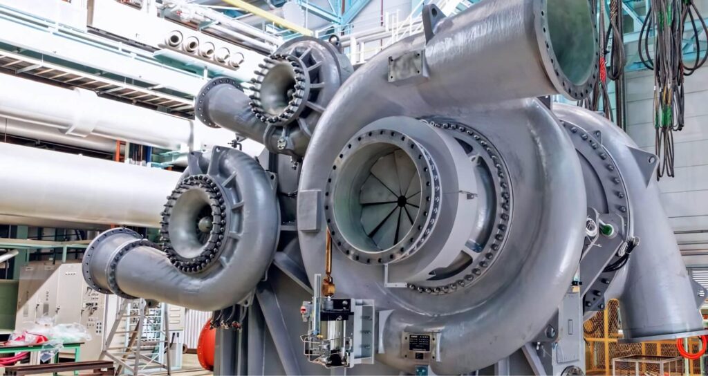
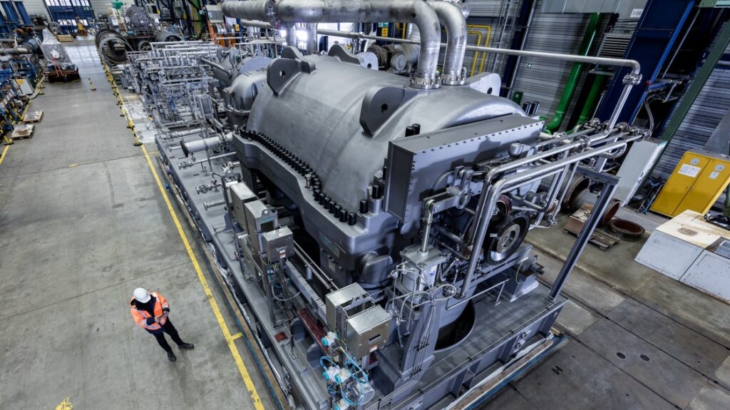
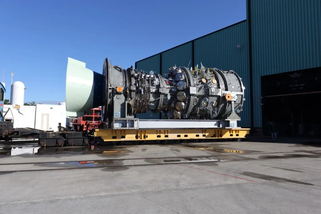
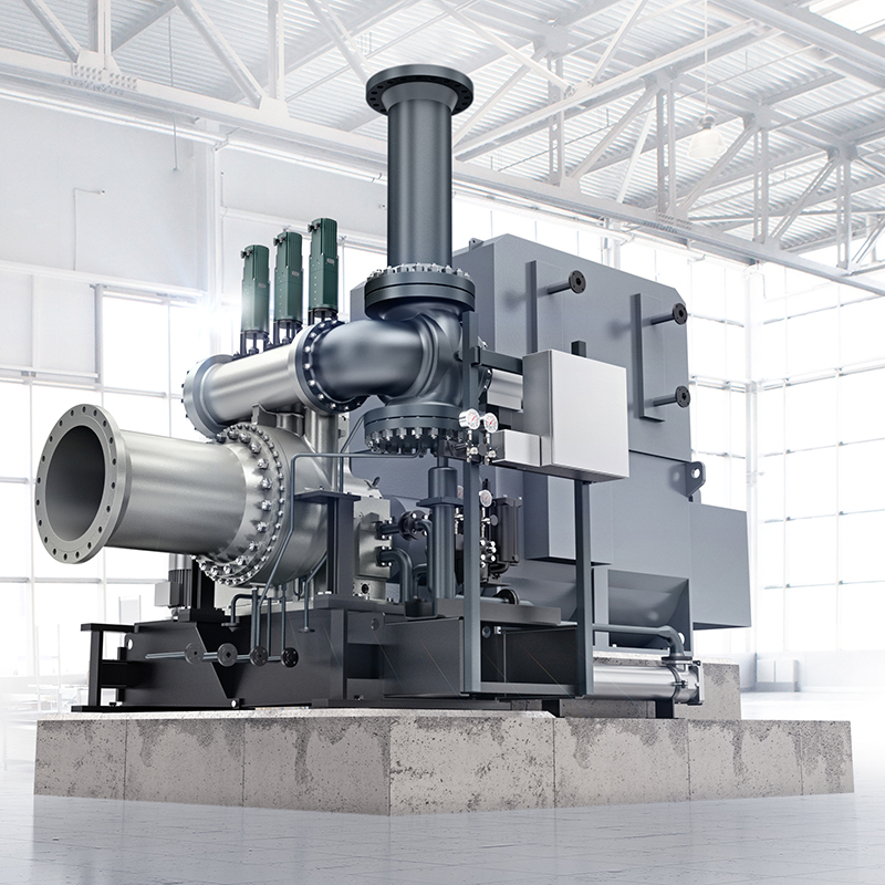
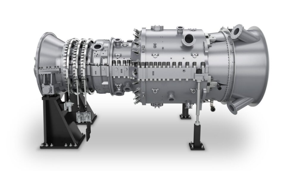
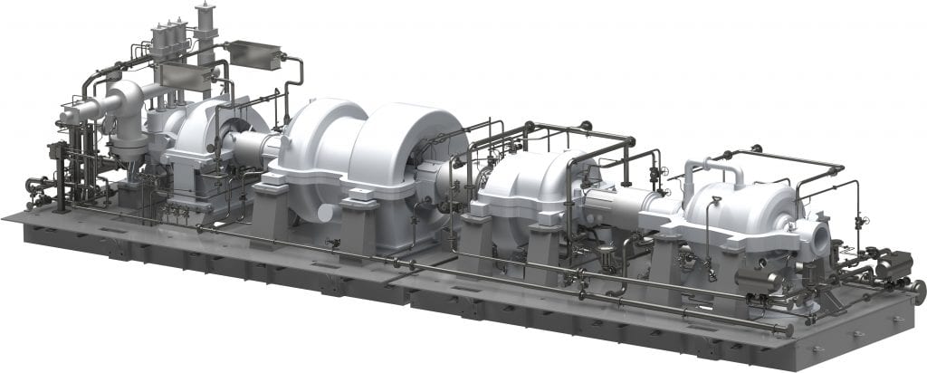
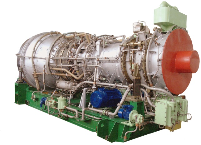
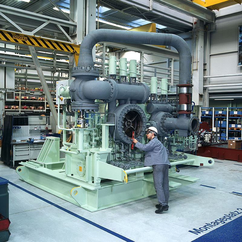
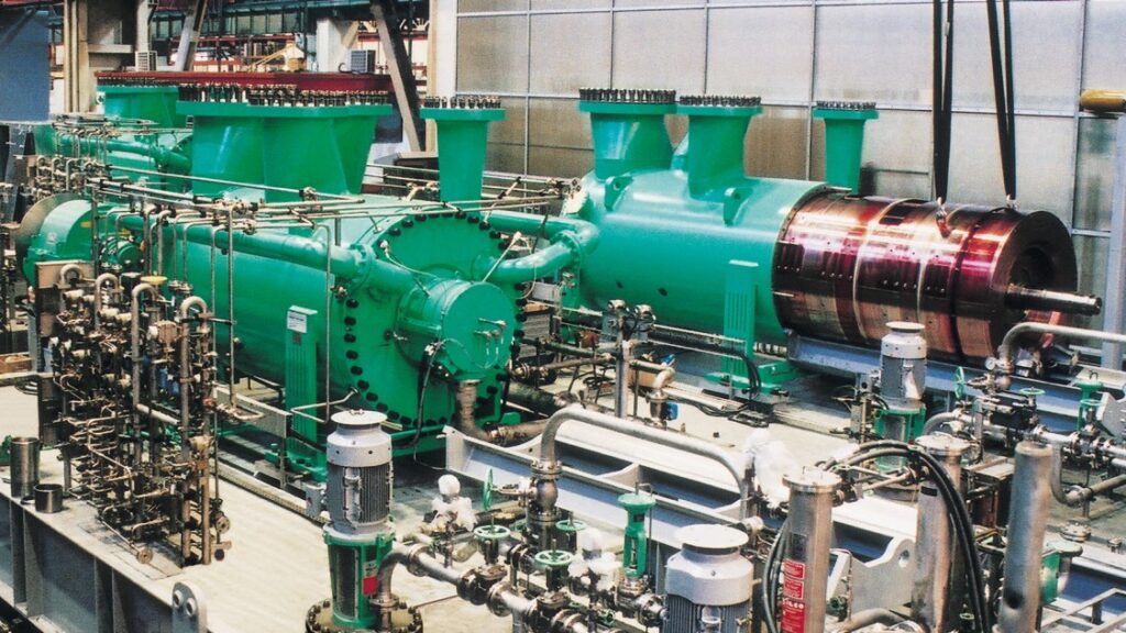
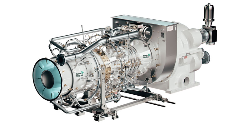
CENTRIFUGAL COMPRESSORS
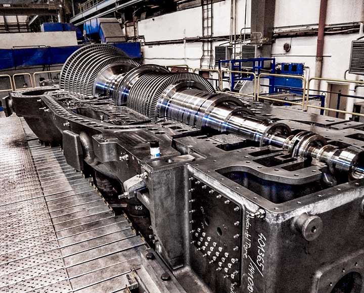
CASING
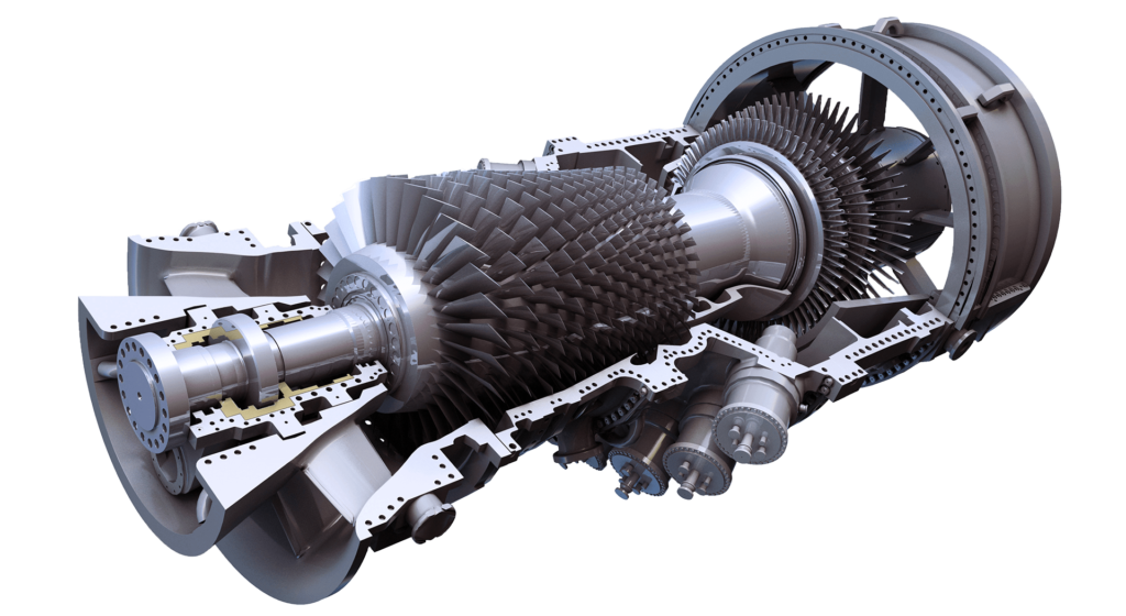
IMPELLERS
SHAFT SEALS (DGS)
Material Selection: The choice of casing material is crucial to ensure reliability and safety. The casing should be made of high-strength materials capable of withstanding the pressures and temperatures experienced during compression. Common materials used include cast iron, carbon steel, stainless steel, and various alloys. The selection depends on factors such as the gas or air being compressed, operating conditions, and corrosion resistance requirements.
Structural Integrity: The casing must be designed to provide structural integrity and withstand the forces generated during operation. It should be able to contain the pressurized gas or air without deformation or leakage. Finite Element Analysis (FEA) and stress analysis techniques are employed to ensure the casing’s structural integrity and determine the appropriate thickness and reinforcement at critical areas.
Pressure Vessel Design Codes: Centrifugal compressor casings are often designed according to relevant pressure vessel design codes, such as ASME (American Society of Mechanical Engineers) Boiler and Pressure Vessel Code. These codes specify design requirements, material standards, fabrication procedures, inspection criteria, and testing methods to ensure the safety and reliability of pressure-containing equipment.
Casing Configuration: The casing design should consider factors such as ease of assembly, maintenance, and accessibility for inspection and repair. It may include features like bolted access doors or removable sections to facilitate internal inspection and component replacement.
Sealing Mechanisms: Proper sealing mechanisms are critical to prevent gas or air leakage from the casing. Casing seals are typically implemented at various locations, such as the casing joints, shaft penetrations, and nozzle connections. These seals may consist of gaskets, packing, labyrinth seals, or mechanical seals, depending on the operating conditions and requirements.
Safety Relief Systems: Centrifugal compressors incorporate safety relief systems to protect against overpressure situations. These systems typically include pressure relief valves that are set to open at a predetermined pressure to safely discharge the gas or air, preventing equipment damage or catastrophic failure.
Corrosion Protection: Corrosion can significantly affect the integrity of the casing. Adequate measures should be taken to protect the casing against corrosive environments, such as coating the internal and external surfaces with corrosion-resistant materials or applying protective coatings.
Non-Destructive Testing (NDT): Non-destructive testing techniques, such as ultrasonic testing, magnetic particle inspection, and radiographic testing, are employed during manufacturing and maintenance to detect any defects or flaws in the casing that could compromise its integrity.
To increase reliability and safety in centrifugal compressor casings, it is essential to follow industry standards and best practices, conduct thorough engineering analysis, employ robust quality control measures during manufacturing, and implement regular inspection, maintenance, and testing protocols throughout the equipment’s lifecycle.
Impeller Geometry: The impeller’s geometry is a key factor in optimizing compressor performance. Design parameters such as the blade shape, curvature, number of blades, and blade angles are carefully determined through computational fluid dynamics (CFD) analysis and empirical data. The impeller geometry should be tailored to the specific gas or air being compressed, flow rate, and pressure requirements to achieve efficient operation.
Material Selection: Impellers are subjected to high rotational speeds and dynamic forces, necessitating the use of materials with excellent mechanical properties. Typically, impellers are made from high-strength alloys, such as stainless steel or titanium, that can withstand the stresses and centrifugal forces experienced during operation. Material selection may also consider factors such as corrosion resistance and temperature resistance.
Balancing: Impellers need to be dynamically balanced to minimize vibrations and ensure smooth operation. Unbalanced forces can lead to excessive vibrations, which can affect the impeller’s performance, decrease efficiency, and potentially lead to mechanical failures. Balancing techniques, such as static and dynamic balancing, are employed during manufacturing to achieve optimal balance.
Clearance Control: The clearance between the impeller and the surrounding components, such as the casing or diffuser, needs to be carefully controlled. Adequate clearance ensures efficient flow while preventing contact and potential damage. Clearances are typically designed to account for thermal expansion, rotor deflection, and manufacturing tolerances.
Blade Coatings: Impeller blades may be coated with protective materials to enhance their durability and resistance to wear, erosion, and corrosion. Coatings such as ceramic or thermal spray coatings can improve the impeller’s lifespan, particularly in applications involving aggressive gases or high-temperature environments.
Stress Analysis: Finite Element Analysis (FEA) is commonly used to analyze the stress distribution and deformation of impellers under different operating conditions. This analysis helps identify potential stress concentrations and areas prone to fatigue or failure. By optimizing the impeller’s design based on stress analysis results, its reliability and safety can be improved.
Aerodynamic Efficiency: Impeller design focuses on maximizing aerodynamic efficiency by minimizing losses due to turbulence and flow separation. CFD simulations are performed to analyze the flow patterns and optimize the impeller’s design for better energy transfer and reduced losses. This results in improved compressor performance and energy efficiency.
Material Inspection and Quality Control: Impellers undergo thorough material inspection during manufacturing to ensure the absence of defects or flaws that could compromise their integrity. Quality control measures, such as non-destructive testing (NDT) techniques like ultrasonic testing or dye penetrant inspection, are employed to verify the impeller’s structural soundness.
To enhance operating functions, reliability, and safety of centrifugal compressors with regard to impellers, it is essential to incorporate advanced engineering techniques, perform rigorous quality control, conduct detailed stress and aerodynamic analyses, and adhere to industry standards and best practices. Regular inspection, maintenance, and monitoring are also necessary to identify any potential issues and ensure the impellers operate optimally throughout their lifespan.
Sealing Mechanism: Special dry gas seals employ a non-contacting sealing mechanism to minimize friction and wear. The seal consists of two primary components: a stationary seal face attached to the casing and a rotating seal face affixed to the compressor shaft. The seal faces are lapped to provide a high-quality sealing surface.
Barrier Gas System: Dry gas seals require a barrier gas system to maintain a positive pressure between the seal faces and prevent the process gas from leaking out. The barrier gas is typically a clean and dry gas, such as nitrogen or compressed air. The barrier gas is supplied at a higher pressure than the process gas, ensuring that any leakage occurs from the process side to the atmosphere.
Secondary Containment: In addition to the primary sealing mechanism, dry gas seals incorporate secondary containment systems to provide an additional layer of safety and prevent process gas leakage to the environment in case of seal failure. The secondary containment can be in the form of a labyrinth or mechanical backup seals.
Ventilation System: Dry gas seals require a ventilation system to control the pressure between the primary and secondary seals. This system ensures that the secondary seal operates at a slightly lower pressure than the primary seal, preventing the process gas from bypassing the primary seal and entering the secondary containment.
Design Considerations: Various design factors influence the performance and reliability of dry gas seals. These include the choice of seal face materials, spring design for maintaining proper face contact, seal face cooling mechanisms (such as fins or circulating coolants), and robust sealing configurations.
Filtration and Purification: The barrier gas supplied to the dry gas seals needs to be filtered and purified to remove any contaminants that could potentially damage the seal faces or affect their performance. Filtration systems, including coalescing filters and particulate filters, are typically employed to ensure the barrier gas is clean and dry.
Condition Monitoring: To enhance reliability and safety, condition monitoring systems are often integrated into centrifugal compressors with dry gas seals. These systems monitor parameters such as seal face temperature, pressure differentials, and gas flow rates. Any abnormal conditions can trigger alarms or shutdown the compressor to prevent seal damage or gas leakage.
Maintenance and Inspection: Regular maintenance and inspection of dry gas seals are critical to ensure their long-term reliability. Maintenance activities may include cleaning and inspection of the seal faces, checking and adjusting the seal face clearances, monitoring the barrier gas supply, and verifying the integrity of the secondary containment system.
To increase the operating functions, reliability, and safety of centrifugal compressors with special dry gas seals, careful engineering and design considerations must be taken into account. This involves selecting appropriate materials, optimizing the sealing mechanism, ensuring proper barrier gas supply and ventilation, implementing secondary containment systems, and integrating condition monitoring. By following these practices and conducting regular maintenance, the performance and safety of the shaft seals can be maximized.
BEARINGS
INLET GUIDE VANES (IGV)
PISTON BALANCE
Bearing Selection: The selection of appropriate radial and axial bearings depends on factors such as load capacity, speed, temperature, and lubrication requirements. High-quality bearings with the necessary load-carrying capacity and durability are chosen to ensure reliable operation.
Load Analysis: Proper load analysis is conducted to determine the radial and axial loads acting on the bearings. This analysis considers factors such as impeller weight, gas or air pressure loads, and unbalanced forces. By accurately estimating the loads, the bearings can be designed and sized accordingly.
Bearing Configuration: The configuration of the bearings, including their arrangement and orientation, is critical for optimal load distribution and stability. Common configurations include single-row or double-row radial bearings and angular contact or thrust bearings for axial loads. Careful consideration is given to bearing alignment and preloading to minimize misalignment and ensure smooth operation.
Lubrication System: Effective lubrication is essential for reducing friction, preventing wear, and dissipating heat. Centrifugal compressors employ lubrication systems to provide a continuous supply of clean and properly cooled lubricant to the bearings. The system may include oil circulation, filtration, cooling, and monitoring to maintain optimal lubrication conditions.
Bearing Material and Coatings: Bearings are typically made from high-quality materials with excellent wear resistance, load capacity, and corrosion resistance. Common materials include steel alloys, such as 52100 or 4140, or specialized bearing materials like ceramic or coated bearings. Surface coatings, such as anti-corrosion or anti-wear coatings, can also be applied to enhance the bearing’s performance and longevity.
Vibration and Stability Analysis: Vibrations can negatively impact bearing performance and lead to premature failure. Engineering analysis techniques, such as finite element analysis (FEA) and dynamic analysis, are employed to evaluate the bearing system’s dynamic behavior, including resonance frequencies and critical speeds. By analyzing the system’s stability, measures can be taken to mitigate potential vibration issues.
Bearing Monitoring and Condition Monitoring Systems: To ensure reliability and safety, bearing monitoring systems and condition monitoring techniques are utilized. These systems continuously monitor various parameters, including temperature, vibration, lubricant condition, and bearing clearances. Any deviations from normal operating conditions can trigger alarms or shutdowns, allowing for timely maintenance and prevention of catastrophic failures.
Maintenance and Inspection: Regular maintenance and inspection of the bearings are essential to ensure their optimal performance and longevity. This may involve activities such as lubricant analysis, visual inspections, measurement of bearing clearances, and replacement of worn-out or damaged bearings.
By considering these engineering and design aspects, centrifugal compressors can achieve better operating functions, increased reliability, and enhanced safety in relation to the radial and axial (thrust) bearings. Proper bearing selection, configuration, lubrication, material choice, vibration analysis, condition monitoring, and maintenance practices are key to achieving optimal bearing performance and ensuring the overall reliability of the compressor.
Aerodynamic Design: The design of inlet guide vanes focuses on optimizing the aerodynamic performance by directing the incoming flow into the compressor impeller. The shape, angle, and curvature of the vanes are carefully designed to ensure smooth and efficient flow while minimizing losses due to turbulence and flow separation.
Variable Vane Angle: Inlet guide vanes are typically adjustable, allowing for variable vane angles. This adjustability enables control over the flow rate and pressure ratio across the compressor. By varying the vane angle, the compressor can adapt to different operating conditions and optimize its performance over a wide range of flow rates.
Vane Actuation Mechanism: The design of the actuation mechanism for the inlet guide vanes is crucial for their reliable operation. Various mechanisms can be used, such as hydraulic, pneumatic, or electric actuators, depending on the application and operating requirements. The actuation system should be robust, precise, and responsive to ensure accurate control of the vane position.
Control System Integration: Inlet guide vanes are typically controlled by a control system that monitors various parameters, such as flow rate, pressure, and temperature. The control system adjusts the vane angle based on the desired operating conditions and system requirements. Integration with the overall compressor control system allows for coordinated operation and optimization of the entire compression process.
Material Selection and Coatings: Inlet guide vanes are exposed to the gas or air flow and need to withstand high temperatures and potentially corrosive environments. The choice of materials, such as high-temperature alloys or coatings, is crucial to ensure their reliability and durability over the compressor’s operating life. Materials with excellent corrosion resistance and thermal stability are typically chosen.
Maintenance and Inspection: Regular maintenance and inspection of the inlet guide vanes are essential to ensure their optimal performance and prevent any potential issues. This may include activities such as visual inspections, cleaning of the vanes, checking for wear or damage, and ensuring proper lubrication and actuation system functionality.
Safety Considerations: Safety features, such as limit switches or position sensors, may be incorporated into the inlet guide vane system to prevent excessive or unintended movements that could compromise the compressor’s performance or integrity. These safety measures help protect the compressor and its associated equipment from potential damage or operational hazards.
Computational Fluid Dynamics (CFD) Analysis: CFD analysis is often employed during the engineering and design phase to evaluate and optimize the performance of the inlet guide vanes. This analysis helps in understanding the flow behavior, pressure distribution, and losses associated with the vanes, allowing for design modifications to enhance efficiency and reliability.
By considering these engineering and design aspects, centrifugal compressors can achieve better operating functions, increased reliability, and enhanced safety with respect to the inlet guide vanes. Optimized aerodynamic design, variable vane angle control, robust actuation mechanisms, material selection, maintenance practices, and safety considerations are crucial for achieving efficient and reliable compressor performance.
Axial Forces and Unbalance: The rotation of the impeller in a centrifugal compressor generates axial forces due to the pressure difference between the inlet and outlet sides. These forces can cause excessive vibration, axial thrust, and increased bearing loads, which can negatively impact the compressor’s performance, reliability, and safety. The piston balance system is designed to counterbalance these axial forces.
Piston Balance Mechanism: The piston balance system consists of pistons or balance drums strategically placed around the impeller to counteract the axial forces. These pistons are connected to the impeller shaft and move axially in response to the pressure difference. By properly configuring the piston balance system, the axial forces generated by the impeller can be balanced and minimized.
Piston Size and Distribution: The size, number, and distribution of the pistons are carefully determined to achieve effective balance. The design considers factors such as the impeller size, flow rate, and pressure conditions. The pistons should be sized and positioned to generate counteracting forces that balance the axial forces generated by the impeller.
Piston Actuation System: The piston balance system may incorporate an actuation mechanism to adjust the position of the pistons. This allows for dynamic balancing during different operating conditions, ensuring optimal performance and reducing wear and fatigue on the impeller shaft and bearings. The actuation system can be hydraulic, pneumatic, or mechanical, depending on the specific application and requirements.
Material Selection: The pistons and related components must be made from high-strength materials capable of withstanding the dynamic forces and pressures experienced during compressor operation. Common materials include steel alloys, such as stainless steel or carbon steel, that offer good strength, fatigue resistance, and corrosion resistance.
Finite Element Analysis (FEA): FEA is often employed during the engineering and design phase to analyze the stress distribution and deformation of the piston balance system. This analysis helps identify potential stress concentrations and areas prone to fatigue or failure. By optimizing the design based on FEA results, the reliability and safety of the piston balance system can be enhanced.
Maintenance and Inspection: Regular maintenance and inspection of the piston balance system are necessary to ensure its optimal performance and prevent any potential issues. This may include activities such as visual inspections, checking for wear or damage, lubrication, and verifying the functionality of the actuation system.
Safety Considerations: Safety features, such as position sensors or limit switches, may be integrated into the piston balance system to prevent excessive or unintended movements that could compromise the compressor’s performance or integrity. These safety measures help protect the compressor and its associated equipment from potential damage or operational hazards.
By considering these engineering and design aspects, centrifugal compressors can achieve better operating functions, increased reliability, and enhanced safety with regard to piston balance. Proper piston sizing and distribution, reliable actuation mechanisms, material selection, maintenance practices, and safety considerations are crucial for achieving stable and efficient compressor operation while minimizing axial forces and associated issues.
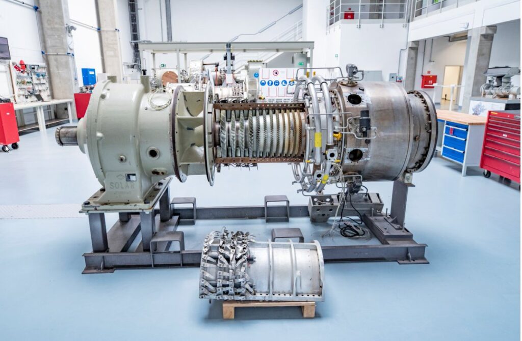
ROTOR
INSTRUMENTATION & CONTROL
DIFFUSERS
Rotor Geometry and Impeller Design: The geometry of the rotor, including the impeller shape, blade profile, and blade angle, is crucial for efficient compression and optimal operating functions. Computational Fluid Dynamics (CFD) analysis and aerodynamic design techniques are employed to optimize the rotor geometry, ensuring proper flow control, minimal losses, and efficient energy transfer.
Material Selection and Strength: The rotor material is carefully chosen based on factors such as strength, fatigue resistance, and corrosion resistance. Common materials include high-strength alloys like stainless steel or titanium. The material should be able to withstand the high rotational speeds, dynamic loads, and the temperature and pressure conditions encountered during operation.
Rotational Speed and Dynamic Balancing: The rotational speed of the rotor needs to be carefully determined to ensure stability, minimize vibration, and prevent fatigue failure. Dynamic balancing techniques are employed during the manufacturing process to reduce unbalance forces and vibrations caused by asymmetry in the rotor mass distribution. Proper balancing improves reliability, reduces stress on bearings, and enhances safety.
Bearings and Support System: The design of the rotor’s bearing system is crucial for supporting the rotor and minimizing friction, wear, and vibration. High-quality radial and axial bearings are used to provide reliable support and reduce losses. The bearing selection and design consider factors such as load capacity, lubrication requirements, and operating conditions. Proper lubrication systems, including oil circulation, filtration, and cooling, are employed to maintain optimal bearing performance and extend their lifespan.
Rotor Dynamics Analysis: Rotor dynamics analysis is performed to evaluate the critical speeds, resonances, and stability of the rotor system. This analysis helps identify potential vibration issues, such as rotor bow, critical speed crossing, or rotor whirl. By optimizing the rotor design based on these analyses, the reliability and safety of the compressor can be increased.
Material Coatings and Surface Treatments: To enhance the rotor’s durability and performance, various coatings and surface treatments can be applied. These may include anti-corrosion coatings, wear-resistant coatings, or surface treatments like shot peening or nitriding. These treatments improve the rotor’s resistance to fatigue, erosion, and corrosive environments.
Maintenance and Inspection: Regular maintenance and inspection of the compressor rotor are essential to ensure its optimal performance and prevent any potential issues. This includes activities such as visual inspections, checking for signs of wear or damage, balancing checks, and monitoring of critical parameters like temperature and vibration.
Safety Considerations: Safety features, such as vibration sensors, temperature monitoring, or bearing condition monitoring systems, can be integrated into the rotor system to detect abnormal operating conditions and trigger alarms or shutdowns. These safety measures help protect the compressor and its associated equipment from potential damage or operational hazards.
By considering these engineering and design aspects, centrifugal compressors can achieve better operating functions, increased reliability, and enhanced safety with regard to the compressor rotor. Optimization of rotor geometry, proper material selection, dynamic balancing, bearing design, rotor dynamics analysis, surface treatments, maintenance practices, and safety considerations are crucial for achieving efficient and reliable compressor operation while minimizing risks and ensuring long-term performance.
Instrumentation Selection: Proper selection of instrumentation devices is essential to monitor critical parameters such as pressure, temperature, flow rate, speed, and vibration. Reliable sensors and transmitters are chosen based on their accuracy, reliability, and suitability for the specific operating conditions of the compressor. These instruments provide real-time data for control and protection purposes.
Control System Architecture: The control system architecture is designed to monitor and regulate the compressor’s operation. It includes a centralized control panel or distributed control system (DCS) that interfaces with various instrumentation devices, actuation mechanisms, and safety systems. The control system can employ programmable logic controllers (PLCs) and human-machine interfaces (HMIs) for efficient operation and user-friendly monitoring.
Safety Interlocks and Shutdown Systems: Safety interlocks and shutdown systems are implemented to protect the compressor from operating beyond safe limits. These systems monitor critical parameters and trigger alarms or initiate emergency shutdowns if abnormal conditions are detected. Examples include high-temperature alarms, low lubrication pressure shutdowns, or overspeed protection.
Sequence Control and Start-up/Shut-down Procedures: Sequence control logic is designed to ensure proper start-up and shut-down procedures for the compressor. This includes control of valves, motor starters, and other auxiliary equipment to follow a predefined sequence that minimizes stress and ensures safe operation. Proper start-up and shut-down procedures help increase the reliability and lifespan of the compressor.
Monitoring and Diagnostics: Advanced monitoring and diagnostic systems are employed to detect and diagnose potential issues or abnormalities in real-time. This may include vibration monitoring, bearing condition monitoring, lubrication system monitoring, or analysis of process parameters. Continuous monitoring allows for early detection of faults and proactive maintenance, reducing the risk of unexpected failures.
Communication and Integration: The instrumentation, control, and protection systems are integrated with the overall plant control system to facilitate seamless communication and data exchange. This integration enables coordination with other equipment and systems, such as power supply, process control, and safety systems. Effective communication and integration enhance overall plant efficiency, reliability, and safety.
Redundancy and Backup Systems: To increase reliability, redundancy can be incorporated into critical instrumentation, control, and protection systems. Redundant sensors, actuators, and control systems ensure that the compressor can continue operating even if a component fails. Backup power supplies and data storage systems are also implemented to prevent data loss or control system failure during power outages or other unforeseen events.
Maintenance and Calibration: Regular maintenance, calibration, and testing of the instrumentation, control, and protection systems are necessary to ensure their accuracy and reliability. Periodic inspections, functional checks, and calibration procedures are conducted to ensure that the systems perform optimally and provide accurate data for monitoring and control.
By considering these engineering and design aspects, centrifugal compressors can achieve better operating functions, increased reliability, and enhanced safety through optimized instrumentation, control, and protection systems. Proper selection of instrumentation, robust control system architecture, safety interlocks, monitoring and diagnostic capabilities, communication and integration, redundancy, and regular maintenance practices are essential for achieving efficient and reliable compressor operation while minimizing risks and ensuring safe and stable performance.
Diffuser Geometry: The geometry of the diffuser is crucial for efficient pressure recovery and minimizing losses. The diffuser shape, including the curvature, cross-sectional area, and expansion angle, is carefully designed to ensure smooth flow transition and minimize flow separation. Computational Fluid Dynamics (CFD) analysis and aerodynamic design techniques are employed to optimize the diffuser geometry for maximum pressure recovery and minimal losses.
Diffuser Channel Design: The design of the diffuser channels, which guide the flow as it expands and decelerates, is important for achieving proper flow distribution and minimizing losses. The channel shape, length, and number of vanes or blades are optimized to control the flow pattern, reduce turbulence, and maintain uniform velocity distribution across the diffuser cross-section.
Aerodynamic Performance: The diffuser design should aim to achieve high pressure recovery and minimal losses. Efficient diffuser designs ensure that the gas or air flow expands uniformly and gradually, converting kinetic energy into pressure energy while minimizing losses due to turbulence and flow separation. Proper diffuser design enhances compressor performance by maximizing the pressure rise and reducing energy losses.
Material Selection: The diffuser material should be selected based on factors such as strength, corrosion resistance, and temperature resistance. Common materials include stainless steel or high-strength alloys capable of withstanding the temperature and pressure conditions experienced in the compressor. Proper material selection ensures the diffuser’s reliability and durability over the compressor’s operating life.
Computational Fluid Dynamics (CFD) Analysis: CFD analysis is often employed during the engineering and design phase to evaluate and optimize the diffuser’s aerodynamic performance. This analysis helps understand the flow behavior, pressure distribution, and losses associated with the diffuser, allowing for design modifications to enhance efficiency and reliability.
Diffuser Inlet and Outlet Conditions: Proper alignment and transition between the diffuser and impeller are crucial for minimizing losses and achieving optimal performance. Smooth transitions, such as volute or scroll designs, are employed to ensure efficient flow entry into the diffuser and smooth flow exit towards the discharge outlet or discharge pipe.
Maintenance and Inspection: Regular maintenance and inspection of the diffuser are necessary to ensure its optimal performance and prevent any potential issues. This may include activities such as visual inspections, checking for wear or damage, cleaning of any fouling or debris, and ensuring proper alignment and sealing with other components.
Safety Considerations: Safety features, such as pressure relief valves or temperature sensors, can be incorporated into the diffuser system to detect abnormal operating conditions and trigger alarms or shutdowns. These safety measures help protect the compressor and its associated equipment from potential damage or operational hazards.
By considering these engineering and design aspects, centrifugal compressors can achieve better operating functions, increased reliability, and enhanced safety through optimized diffuser design. Proper diffuser geometry, efficient channel design, material selection, CFD analysis, maintenance practices, and safety considerations are crucial for achieving efficient and reliable compressor operation while minimizing losses and ensuring stable performance.