Alberto Mtz Llaurado

Consulting – TECHNOLOGY FOR POWER AUGMENTATION IN GAS TURBINES

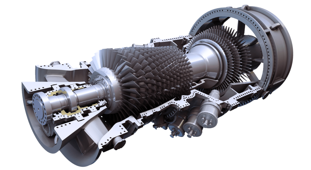
TECHNOLOGY ABOUT POWER AUGMENTATION IN GAS TURBINES

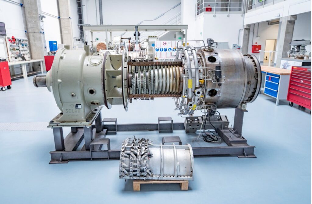
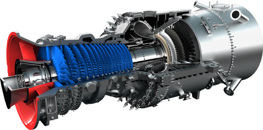
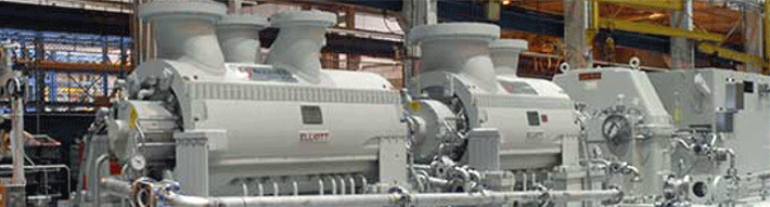
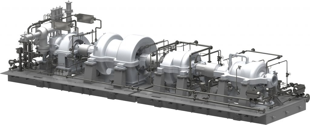
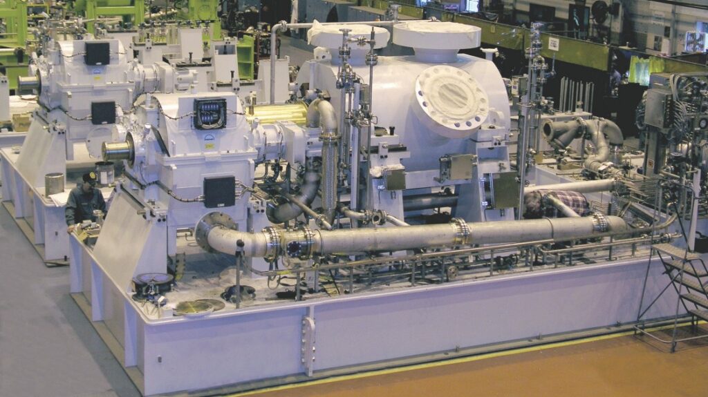
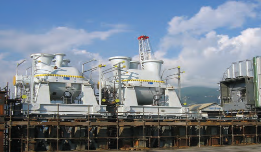
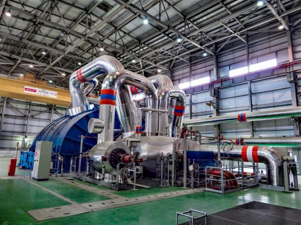
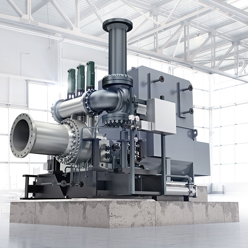
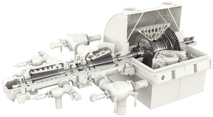
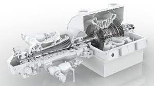
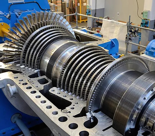
There are several technologies available that can increase or augment the output power in gas turbines, including:

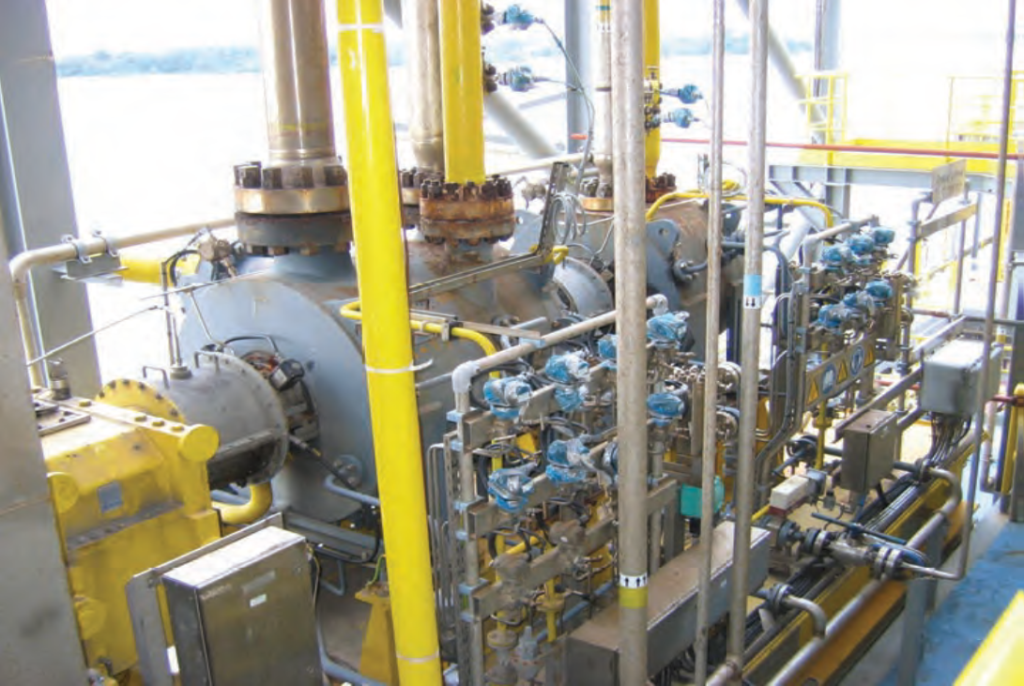
  1. Water injection: Water injection is a process that involves injecting water into the combustion chamber of a gas turbine to increase power output and improve efficiency. Water injection can reduce the temperature of the combustion gases, which reduces the NOx emissions, increases the mass flow rate of air, and reduces the compressor discharge temperature.

  2. Steam injection: Steam injection is a process that involves injecting steam into the combustion chamber of a gas turbine to increase power output and efficiency. Steam injection increases the mass flow rate of air, reduces the compressor discharge temperature, and reduces the NOx emissions.

  3. Inlet air cooling: Inlet air cooling is a process that involves cooling the incoming air before it enters the gas turbine. Cooling the air increases the mass flow rate of air, which increases the power output and efficiency of the gas turbine. Inlet air cooling can be achieved using different methods, such as evaporative cooling, absorption cooling, and mechanical cooling.

  4. Compressor intercooling: Compressor intercooling is a process that involves cooling the compressed air between compressor stages to reduce the compressor discharge temperature. Lowering the compressor discharge temperature increases the mass flow rate of air, which increases the power output and efficiency of the gas turbine.

  5. Turbine blade cooling: Turbine blade cooling is a process that involves cooling the turbine blades to reduce the temperature of the turbine components and increase their lifespan. The cooling can be achieved using different methods, such as film cooling, impingement cooling, and convective cooling.

  6. Exhaust heat recovery: Exhaust heat recovery is a process that involves recovering the waste heat from the exhaust gases of the gas turbine and using it to produce additional power or to provide heating or cooling.

All of these technologies can improve the efficiency, performance, reliability, availability, and safety of gas turbines. However, each technology has its own benefits and drawbacks, and the most suitable technology will depend on the specific requirements of the gas turbine and its operating conditions. Careful evaluation and analysis should be conducted before implementing any of these technologies to ensure they are applied in the most effective and efficient way possible.

courtesy by GE

LIMITS IN ENGINEERING & DESIGN TO INCREASE THE OUTPUT POWER

While there are several technologies available to increase or augment the output power in gas turbines, there are also limits in engineering and design that must be considered. These limits can affect the efficiency, performance, reliability, availability, and safety of gas turbines. Some of the main limits include:

  1. Material limitations: The use of water injection, steam injection, or cooling water systems at inlet air can increase the temperature and pressure within the gas turbine, which can put stress on the materials used in the turbine. This stress can cause mechanical failure and reduce the lifespan of the turbine. Therefore, the materials used in the turbine must be carefully selected and designed to withstand the increased stress.

  2. Combustion instability: The use of water injection or steam injection can affect the combustion stability within the gas turbine. The presence of water or steam in the combustion chamber can change the fuel-air mixture, which can cause instability in the combustion process. This instability can lead to reduced performance and reliability of the gas turbine.

  3. Environmental limits: The use of water injection or cooling water systems can have environmental impacts, such as water usage and discharge. These impacts must be considered in the design and operation of the gas turbine to ensure compliance with environmental regulations and minimize the impact on local ecosystems.

  4. Cost limitations: The implementation of these technologies can involve significant costs in terms of design, construction, and operation. These costs must be carefully evaluated against the expected benefits to ensure that the investment is justified.

Overall, the limits in engineering and design for increasing or augmenting the output power in gas turbines must be carefully evaluated and addressed to ensure the efficiency, performance, reliability, availability, and safety of the gas turbine. The implementation of these technologies should be approached with a holistic view that considers the technical, environmental, and economic factors to maximize the benefits and minimize the risks.

courtesy by MAN

WHY, WHEN, WHERE TO INCREASE OR AUGMENT THE OUTPUT POWER IN GAS TURBINES

The reasons for increasing or augmenting the output power in gas turbines using technologies such as water injection, steam injection, or cooling water systems at inlet air can vary depending on the specific situation. Generally, these technologies are implemented to improve the efficiency, performance, reliability, availability, and safety of gas turbines. The following are some common reasons for their implementation:

  1. Efficiency improvement: By increasing the power output of a gas turbine, the efficiency of the power generation process can be improved. This can lead to reduced fuel consumption, lower emissions, and lower operating costs.

  2. Peak demand management: During periods of peak demand for electricity, it may be necessary to increase the power output of gas turbines to meet the increased demand. Technologies such as water or steam injection can provide a quick and effective way to increase power output during these periods.

  3. Fuel flexibility: In some cases, the use of water or steam injection can allow gas turbines to operate on lower quality fuels. This can increase the flexibility of the power generation system and reduce dependence on a single fuel source.

  4. Maintenance reduction: By increasing the power output of a gas turbine, the number of turbines required to meet power demand can be reduced. This can result in lower maintenance costs and improved reliability.

The specific technology and implementation approach will depend on the particular gas turbine and its operating conditions. The decision to implement these technologies should be based on a careful evaluation of the technical, environmental, and economic factors. The implementation of these technologies should also be done in accordance with industry standards and regulations to ensure safety and reliability.

PROCEDURES, ACTIONS, STUDIES, MITIGATION, RECOMMENDATIONS TO INCREASE OR AUGMENT THE OUTPUT POWER IN GAS TURBINES

The procedures, actions, studies, mitigation, and recommendations to increase or augment the output power in gas turbines using technologies such as water injection, steam injection, or cooling water systems at inlet air can vary depending on the specific situation. However, the following are some general steps and considerations:

  1. Feasibility study: A feasibility study should be conducted to determine the technical, economic, and environmental feasibility of implementing these technologies. This study should consider the specific gas turbine, operating conditions, and regulatory requirements.

  2. Design and engineering: Once the feasibility study has been completed, the gas turbine system should be designed and engineered to incorporate the chosen technology. This includes modifications to the gas turbine, control system, and supporting infrastructure.

  3. Testing and commissioning: Before the system is put into operation, testing and commissioning should be conducted to ensure that the modifications have been successfully implemented and that the system is operating as expected.

  4. Ongoing monitoring and maintenance: Once the system is operational, ongoing monitoring and maintenance should be conducted to ensure that the system is operating safely and reliably. This includes monitoring performance metrics, conducting regular inspections and maintenance, and addressing any issues that arise.

  5. Mitigation of risks: Implementation of these technologies may introduce new risks to the gas turbine system. Mitigation measures should be implemented to ensure that these risks are identified and managed effectively. This may include developing contingency plans, conducting risk assessments, and implementing appropriate safety measures.

  6. Industry standards and regulations: The implementation of these technologies should be done in accordance with industry standards and regulations to ensure safety and reliability. These standards and regulations may include those related to gas turbine design, installation, operation, and maintenance.

Overall, the successful implementation of these technologies requires careful planning, design, testing, and ongoing maintenance. The goal should be to increase power output while ensuring the reliability, availability, and safety of the gas turbine system.

courtesy by SOLAR TURBINES

Consulting – RECENT TECHNOLOGY IN MATERIALS FOR GAS TURBINES

RECENT TECHNOLOGY IN MATERIALS FOR GAS TURBINES

courtesy by ANSALDO

Gas turbines are critical components in the power generation and aviation industries. They rely on high-temperature materials such as alloys to withstand the extreme operating conditions. However, these materials are susceptible to corrosion, erosion, and oxidation, which can lead to significant performance degradation, safety hazards, and costly downtime.

To address these challenges, researchers have developed various coating barriers, ceramics, and other advanced materials that can enhance the performance and reliability of gas turbine components. These materials are designed to improve efficiency, reduce emissions, and extend the life of critical parts such as turbine and compressor blades, wheels, combustors, transition pieces, and exhaust sections.

One approach to improving the durability of gas turbine components is through the use of thermal barrier coatings (TBCs). TBCs are typically made from ceramic materials that can withstand high temperatures and thermal stresses. They are applied to the surface of the component to create a barrier between the hot gases and the underlying metal. This reduces heat transfer to the metal, which helps to reduce thermal fatigue, oxidation, and corrosion.

Another strategy is to use advanced alloys that offer better high-temperature performance and resistance to corrosion and fatigue. For example, nickel-based superalloys are commonly used in gas turbine components due to their excellent high-temperature strength and resistance to creep, corrosion, and oxidation. Additionally, some alloys are designed to have a low coefficient of thermal expansion, which can help to reduce thermal stresses and extend the life of the component.

In addition to materials selection, researchers are also exploring advanced manufacturing techniques to improve the performance and reliability of gas turbine components. For example, additive manufacturing (AM) can be used to produce complex geometries with improved performance and reduced weight. AM also allows for the production of customized components that are tailored to specific operating conditions and requirements.

Overall, ongoing research and development in the field of materials science and engineering are critical for improving the efficiency, reliability, safety, and performance of gas turbine components. By developing advanced materials and manufacturing techniques, researchers can help to reduce costs, improve performance, and extend the life of gas turbines in both new projects and existing plants.

LIMITS IN ENGINEERING & DESIGN IN MATERIALS

Despite ongoing research and development in the field of materials science and engineering, there are still some limits in engineering and design when it comes to critical materials used in gas turbines.

One of the key challenges is finding materials that can withstand the extreme operating conditions in gas turbines. These conditions include high temperatures, thermal cycling, corrosion, erosion, and mechanical stresses. While some materials are designed to perform well under certain conditions, it can be difficult to find materials that can meet all of the requirements for a specific gas turbine application.

In addition to material selection, there are also limitations in the design of gas turbine components. For example, it can be difficult to design components with complex geometries that can withstand the high stresses and temperatures in gas turbines. This is particularly challenging for components that require cooling, such as turbine blades and vanes. Designing effective cooling schemes that can keep the components within a safe operating temperature range while also maintaining structural integrity is a complex task that requires careful consideration of many factors.

Another limitation in engineering and design is the cost of developing and testing new materials and components. The development of new alloys, thermal barrier coatings, and ceramics requires significant investment in research and development, testing, and certification. This can be a barrier for smaller companies or organizations that may not have the resources to invest in these activities.

Finally, there are also limitations in the manufacturing processes used to produce gas turbine components. Some manufacturing techniques, such as casting and forging, can result in components with defects that can lead to premature failure. It can also be difficult to achieve the necessary dimensional accuracy and surface finish required for gas turbine components. Advances in additive manufacturing have shown promise in overcoming some of these limitations, but further research is needed to fully understand the capabilities and limitations of these techniques.

Overall, while there have been significant advances in the development of critical materials used in gas turbines, there are still limitations in engineering and design that must be addressed to further improve the efficiency, reliability, safety, and performance of these components. Addressing these limitations requires ongoing research and development, as well as collaboration between materials scientists, engineers, and manufacturers.

WHY, WHEN, WHICH & WHERE TO APPLY ABOUT CRITICAL MATERIALS

WHY: The use of critical materials such as new alloys, thermal coating barriers, and ceramics in gas turbines is essential for improving their efficiency, performance, and reliability. Gas turbines operate in extreme conditions that can cause significant wear and damage to components, leading to reduced efficiency, higher maintenance costs, and increased risk of failures. Critical materials are designed to withstand these conditions and protect components from wear, corrosion, and thermal stresses, thus reducing downtime and increasing the lifespan of the gas turbine.

WHEN: Critical materials should be applied during the design and construction phase of gas turbine projects. This includes both new projects and upgrades to existing plants. During the design phase, engineers should carefully consider the operating conditions and requirements of the gas turbine and select materials that are suitable for the specific application. During construction, components should be manufactured with the selected materials and coatings to ensure their optimal performance.

WHICH: The selection of critical materials will depend on the specific application of the gas turbine. For example, for high-temperature applications, nickel-based superalloys are commonly used due to their excellent high-temperature strength and resistance to corrosion and oxidation. Thermal barrier coatings made from ceramics can also be used to reduce heat transfer and improve the lifespan of components. For components that require cooling, such as turbine blades, special alloys with good thermal conductivity can be used to improve heat dissipation.

WHERE: Critical materials should be applied in all critical components of gas turbines, including turbine and compressor blades, wheels, combustors, transition pieces, and exhaust sections. These components are subject to extreme operating conditions and require materials that can withstand high temperatures, corrosion, and mechanical stresses. The selection of materials should be carefully considered for each component based on its specific requirements and operating conditions. In addition, coatings such as thermal barrier coatings should be applied to the surface of components to protect them from wear and damage.

courtesy by GE

PROCEDURES, ACTIONS, STUDIES, MITIGATION, RECOMMENDATIONS USING NEW MATERIALS

To ensure the successful application of critical materials such as new alloys, thermal coating barriers, and new ceramics in gas turbines, the following procedures, actions, studies, and recommendations should be applied:

  1. Conduct a thorough risk assessment: Before selecting critical materials, it’s essential to conduct a risk assessment to identify potential failure modes, causes, and consequences. The risk assessment should consider both the design and operating conditions of the gas turbine.

  2. Select the appropriate materials: Based on the risk assessment, select the appropriate critical materials for each component of the gas turbine. The selection should be based on their ability to withstand the specific operating conditions and requirements of each component.

  3. Conduct material testing and validation: Critical materials should be thoroughly tested and validated to ensure that they meet the required standards and specifications. This testing should include mechanical, thermal, and chemical testing to ensure that the materials can withstand the extreme conditions of gas turbine operation.

  4. Apply thermal barrier coatings: For high-temperature applications, thermal barrier coatings should be applied to the surface of components to protect them from thermal stresses and improve their lifespan.

  5. Monitor and maintain components: Once critical materials have been applied, regular monitoring and maintenance should be conducted to ensure that components are performing as expected. This monitoring should include regular inspections, vibration analysis, and thermal imaging.

  6. Conduct failure analysis: In the event of a failure, a thorough failure analysis should be conducted to identify the root cause and develop corrective actions. This analysis should include both physical and metallurgical analysis of failed components.

  7. Implement corrective actions: Based on the findings of the failure analysis, implement corrective actions to prevent similar failures in the future. These corrective actions may include changes to the design, selection of different materials, or changes to the maintenance procedures.

  8. Continuous improvement: Finally, continuous improvement should be implemented to ensure that critical materials and components are continually optimized for improved efficiency, performance, reliability, and safety.

By following these procedures, actions, studies, and recommendations, the successful application of critical materials in gas turbines can be achieved, improving efficiency and performance while reducing the risk of critical failures in new projects and existing plants in power generation and oil and gas industries.

courtesy by GE

Consulting – LOAD SHARING SYSTEMS

LOAD SHARING SYSTEMS IN CENTRIFUGAL COMPRESSORS

courtesy by ELLIOTT

ADVANTAGES & DISADVANTAGES OF A LOAD SHARING SYSTEM IN CENTRIFUGAL COMPRESSORS

Advantages of Load Sharing Systems Associated with Anti-Surge Control & Protection Systems in Centrifugal Gas Compressors, Operating in Parallel with Three or More Compressors:

  1. Improved Reliability: Load-sharing systems distribute the load evenly among multiple compressors, reducing the strain on individual units and enhancing overall system reliability. This helps prevent excessive wear and tear on components, reducing the risk of unexpected failures and unplanned downtime.

  2. Increased Availability: Load-sharing systems ensure that there is redundancy in the compressor system. In the event of a failure or maintenance requirement on one compressor, the remaining compressors can continue to operate, ensuring a continuous supply of gas and maintaining system availability.

  3. Enhanced Safety: Anti-surge control and protection systems work in conjunction with load-sharing systems to prevent surge, a potentially destructive condition that can occur when flow rates decrease below a certain threshold. By implementing load-sharing systems, the risk of surge-induced failures is minimized, improving the safety and reliability of the compressors.

  4. Environmental Risk Mitigation: Load-sharing systems optimize the operation of multiple compressors, allowing for more efficient and effective gas compression processes. This can lead to reduced energy consumption, lower greenhouse gas emissions, and improved environmental performance, contributing to the mitigation of environmental risks.

  5. Scalability and Flexibility: Load-sharing systems provide scalability by allowing the addition or removal of compressors as per the operational requirements. This flexibility enables efficient system expansion or contraction based on the changing demands of the oil, gas, and petrochemical industries.

Disadvantages of Load Sharing Systems Associated with Anti-Surge Control & Protection Systems in Centrifugal Gas Compressors, Operating in Parallel with Three or More Compressors:

  1. Complex System Design: Implementing load-sharing systems in parallel configurations with multiple compressors requires careful design considerations, including the integration of control systems, monitoring devices, and communication networks. This complexity can increase the initial engineering and installation costs, as well as the maintenance and troubleshooting efforts.

  2. Increased System Complexity: Load-sharing systems in parallel configurations add complexity to the overall compressor system, involving additional control algorithms, interconnections, and communication interfaces. This complexity may require specialized training for operators and maintenance personnel to effectively operate and maintain the system.

  3. Synchronization Challenges: Load-sharing systems operating in parallel with three or more compressors require precise synchronization between the compressors to ensure equal load distribution. Achieving and maintaining synchronization can be challenging, especially considering the potential differences in response times and control settings among the compressors.

  4. Cost Considerations: The implementation of load-sharing systems in parallel configurations may involve additional capital expenses, including the installation of sensors, control systems, and communication infrastructure. The cost of implementing and maintaining these systems should be carefully evaluated against the potential benefits and the criticality of the compressor system.

  5. Reliance on Control Systems: Load-sharing systems heavily depend on the performance and reliability of control systems. Any malfunctions or failures in the control system can impact load sharing and surge protection functionality, potentially leading to operational issues or system failures.

Proper design, installation, and maintenance practices, along with a thorough evaluation of the specific requirements and cost-benefit considerations, are essential for successfully implementing load-sharing systems associated with anti-surge control and protection systems in centrifugal gas compressors operating in parallel with three or more compressors. By addressing the associated challenges and leveraging the advantages, these systems can significantly improve reliability, availability, and safety while minimizing environmental risks and critical failures or unscheduled shutdowns.

LIMITATIONS IN ENGINEERING & DESIGN ABOUT LOAD SHARING SYSTEMS

Limitations in Engineering & Design for Load Sharing Systems Operating in Parallel with Three or More Compressors, Associated with Anti-Surge Control & Protection Systems in Centrifugal Gas Compressors:

  1. System Complexity and Integration: Implementing load sharing systems in parallel configurations with multiple compressors requires careful system integration and coordination. The design and engineering process must consider factors such as compressor specifications, control system compatibility, communication protocols, and synchronization requirements. The complexity of integrating these components can increase the risk of design errors, system malfunctions, and operational challenges.

  2. Control System Coordination: Achieving proper coordination and synchronization between multiple compressors in a load sharing system can be challenging. Each compressor needs to be effectively controlled and monitored to ensure equal load distribution and prevent surge. The design of control algorithms and the configuration of control parameters need to be carefully calibrated to ensure smooth operation and prevent issues such as instability or oscillations.

  3. Communication and Interconnection Challenges: Load sharing systems rely on effective communication and interconnection between compressors, control systems, and monitoring devices. Implementing a reliable and robust communication infrastructure is crucial to enable real-time data exchange and control signals. Challenges may arise due to signal delay, data loss, communication errors, or compatibility issues between different components or systems.

  4. Maintenance and Troubleshooting: Load sharing systems introduce additional complexity and interconnectedness, which can make maintenance and troubleshooting more challenging. Proper training and expertise are required to diagnose and address issues related to load sharing, control system performance, and synchronization. The availability of skilled personnel and access to spare parts can be critical for maintaining the reliability and availability of the system.

  5. Initial Cost and Investment: Implementing load sharing systems in parallel configurations with multiple compressors involves additional engineering, equipment, and installation costs compared to single-compressor systems. The cost of sensors, control systems, communication infrastructure, and associated hardware and software should be carefully evaluated against the potential benefits and the criticality of the compressor system.

  6. Scalability and Flexibility: Load sharing systems in parallel configurations may have limitations in terms of scalability and flexibility. Adding or removing compressors from the system may require reconfiguration of control algorithms and recalibration of control parameters. Changes in the system may also require adjustments to the communication infrastructure and control system interfaces.

  7. Compatibility with Existing Systems: Retrofitting load sharing systems in existing industrial plants may pose challenges due to compatibility issues with the existing compressor units, control systems, and infrastructure. Integration of load sharing systems may require modifications or upgrades to existing equipment and systems, which can add complexity and cost.

Careful consideration of these limitations is crucial during the engineering and design phase of load sharing systems operating in parallel with three or more compressors. Thorough analysis, feasibility studies, and close collaboration between compressor manufacturers, control system suppliers, and engineering teams are essential to ensure the successful implementation of load sharing systems. Addressing these limitations can help improve reliability, availability, and safety in industrial plants, mitigate environmental risks, and minimize the likelihood of critical failures or unscheduled shutdowns.

courtesy by MAN

WHY, WHEN, WHERE, WHAT, WHICH, AND HOW TO APPLY LOAD SHARING SYSTEMS IN CENTRIFUGAL COMPRESSORS

Engineering & Design Considerations for Load Sharing Systems Operating in Parallel with Three or More Compressors, with a Focus on Anti-Surge Control & Protection Systems in Centrifugal Gas Compressors:

Why to Apply:

  1. Improve Reliability: Load sharing systems help distribute the load evenly among multiple compressors, reducing the strain on individual units and improving overall system reliability. This ensures that the compressors operate within their optimal range and minimizes the risk of failure or breakdown.

  2. Enhance Availability: Load sharing systems increase the availability of compressed gas by allowing for redundancy. If one compressor requires maintenance or experiences a failure, the remaining compressors can compensate and maintain the required gas flow. This reduces downtime and ensures uninterrupted operation.

  3. Ensure Safety: Load sharing systems, when properly designed, help prevent surge, which is a dangerous phenomenon that can damage the compressor and downstream equipment. By implementing anti-surge control and protection systems in conjunction with load sharing, the risk of surge is mitigated, ensuring the safety of the equipment and personnel.

When to Apply: Load sharing systems with anti-surge control and protection should be considered:

  • When there is a requirement for high gas flow rates that cannot be met by a single compressor.
  • In applications where maintaining continuous operation is critical, such as in oil, gas, and petrochemical industries.
  • For existing industrial plants that are experiencing reliability issues, unscheduled shutdowns, or critical failures.
  • In new projects where reliability, availability, and safety are primary concerns.

Where to Apply: Load sharing systems can be applied in various industrial settings, including:

  • Oil refineries and petrochemical plants.
  • Natural gas processing and transmission facilities.
  • Power generation plants utilizing gas turbines.
  • Compressed air systems in manufacturing and industrial facilities.

What and Which Design Considerations:

  1. Compressor Selection: Choose centrifugal gas compressors that are suitable for load sharing applications and have compatible control systems. Consider factors such as compressor capacity, efficiency, surge margin, and interstage pressure ratios to ensure the compressors can handle the required gas flow and operate reliably in parallel.

  2. Control System Design: Develop a comprehensive control system design that integrates the load sharing and anti-surge control functionalities. This includes implementing advanced control algorithms, surge detection and prevention strategies, and reliable communication systems to ensure coordinated operation and protection against surge.

  3. Load Sharing Strategy: Determine the load sharing strategy that suits the specific application. This may involve using a master/slave configuration or implementing a decentralized control approach. Consider factors such as compressor performance, operational demands, and system response characteristics when designing the load sharing strategy.

  4. Safety and Protection Systems: Incorporate robust anti-surge protection systems to detect and prevent surge events. This includes surge control valves, surge detection algorithms, and protective shutdown mechanisms. Ensure that these systems are properly designed, calibrated, and integrated with the overall control system.

How to Apply:

  1. Feasibility Study: Conduct a feasibility study to assess the suitability and benefits of implementing load sharing systems with anti-surge control. Evaluate the existing system, operational requirements, and potential risks to determine if load sharing is a viable solution.

  2. Detailed Engineering: Engage a team of experienced engineers to develop a detailed engineering design based on the specific requirements and constraints of the application. This includes system sizing, component selection, control system design, and safety system integration.

  3. Testing and Commissioning: Perform rigorous testing and commissioning to verify the performance and functionality of the load sharing system. This includes simulation studies, hardware-in-the-loop testing, and field testing to ensure proper system operation and reliability.

  4. Monitoring and Maintenance: Implement a robust monitoring and maintenance program to ensure the continued performance of the load sharing system. Regular inspections, calibration, and preventive maintenance activities should be carried out to identify and address any potential issues before they escalate into failures or shutdowns.

By applying these engineering and design principles, load sharing systems with anti-surge control and protection can significantly improve the reliability, availability, and safety of centrifugal gas compressors in industrial plants. These systems help avoid critical failures, unscheduled shutdowns, and environmental risks while ensuring continuous operation and efficient gas flow.

PROCEDURES, ACTIONS, STUDIES, MITIGATIONS, RECOMMENDATIONS TO USE LOAD SHARING SYSTEMS

Procedures, Actions, Studies, Mitigations, and Recommendations for Implementing Load Sharing Systems with Anti-Surge Control & Protection in Centrifugal Gas Compressors:

  1. Feasibility Study:
  • Conduct a feasibility study to evaluate the technical and economic viability of implementing a load-sharing system with anti-surge control.
  • Assess the existing system, including the number and capacity of compressors, operational requirements, and surge control measures currently in place.
  • Identify potential benefits, risks, and challenges associated with the proposed load-sharing system.
  1. System Design:
  • Develop a detailed engineering design that considers the specific requirements of the application and the operating conditions.
  • Determine the number of compressors needed for load sharing and their respective capacities.
  • Select appropriate control algorithms, sensors, and actuators to ensure effective anti-surge control and protection.
  • Integrate the load-sharing system with the existing control and safety systems in the plant.
  1. Surge Control and Protection:
  • Conduct surge studies and simulations to understand the surge behavior of the compressors and determine the surge margin.
  • Design surge control strategies, including surge detection algorithms, surge control valves, and surge protection measures.
  • Implement reliable surge control and protection systems to prevent surge events and protect the compressors from damage.
  • Conduct performance tests to validate the surge control and protection system’s effectiveness.
  1. Control System Integration:
  • Develop a comprehensive control system that integrates the load-sharing functionality with the anti-surge control and protection systems.
  • Implement a centralized or decentralized control architecture based on the specific requirements and system characteristics.
  • Ensure seamless communication and coordination between the compressors and the control system.
  • Implement redundancy and fail-safe mechanisms in the control system to enhance reliability and safety.
  1. Monitoring and Maintenance:
  • Install appropriate monitoring and diagnostic systems to continuously assess the health and performance of the compressors and the load-sharing system.
  • Implement condition monitoring techniques to detect any deviations or anomalies that could indicate potential failures or operational issues.
  • Regularly calibrate and maintain the sensors, actuators, and control algorithms to ensure accurate and reliable operation.
  • Establish a comprehensive maintenance program that includes preventive maintenance, inspection, and testing to minimize the risk of failures and unscheduled shutdowns.
  1. Training and Documentation:
  • Provide comprehensive training for operators and maintenance personnel on the proper operation and maintenance of the load-sharing system and anti-surge control measures.
  • Develop detailed documentation, including operating procedures, maintenance manuals, and troubleshooting guides, to ensure consistency and knowledge transfer.
  1. Continuous Improvement:
  • Conduct periodic reviews and assessments of the load-sharing system’s performance, reliability, and effectiveness.
  • Analyze operational data and feedback to identify areas for improvement and optimize system performance.
  • Stay updated with the latest advancements in load sharing and anti-surge control technologies and implement improvements accordingly.

By following these procedures, actions, studies, mitigations, and recommendations, the implementation of load-sharing systems with anti-surge control and protection in centrifugal gas compressors can improve reliability, availability, and safety in existing industrial plants and new projects in the oil, gas, and petrochemical industries. These measures help avoid environmental risks, critical failures, and unscheduled shutdowns, ensuring continuous and efficient operation of the compressors.

courtesy by SIEMENS

Consulting – Carbon Capture & Storage – Centrifugal Compressors

CARBON CAPTURE & STORAGE (CCS) - CENTRIFUGAL COMPRESSORS

ADVANTAGES & DISADVANTAGES IN "CCS" WITH CENTRIFUGAL COMPRESSORS

Centrifugal compressors offer several advantages when used for compressing and storing CO2 underground in the oil, gas, and petrochemical industries. However, there are also disadvantages to consider. Let’s explore both sides:

Advantages of Centrifugal Compressors for CO2 Compression and Storage:

  1. High Efficiency: Centrifugal compressors are known for their high efficiency in converting power into compressed gas. This efficiency is crucial when compressing CO2 for storage, as it minimizes energy consumption and reduces operational costs.

  2. Compact Design: Centrifugal compressors have a relatively compact design compared to other types of compressors. This makes them suitable for installations where space is limited, such as offshore platforms or existing industrial facilities.

  3. Wide Operating Range: Centrifugal compressors have a wide operating range, allowing them to handle varying gas flows and pressures effectively. This flexibility is beneficial when dealing with fluctuating CO2 production rates or changing storage requirements.

  4. Low Maintenance Requirements: Compared to reciprocating compressors, centrifugal compressors generally have lower maintenance requirements. They have fewer moving parts and require less frequent inspections, resulting in reduced downtime and increased reliability.

Disadvantages of Centrifugal Compressors for CO2 Compression and Storage:

  1. Capital Cost: Centrifugal compressors tend to have higher upfront capital costs compared to other compressor types. The complexity of their design, coupled with the need for specialized materials and manufacturing processes, can contribute to the overall expense of implementing a centrifugal compressor system.

  2. Sensitivity to Process Conditions: Centrifugal compressors are sensitive to changes in process conditions, such as gas composition, temperature, and pressure. Variations outside their design parameters can affect performance and efficiency, potentially leading to reduced reliability and increased risk of failure.

  3. Limited Compression Ratio: Centrifugal compressors have a limited compression ratio compared to some other compressor types, such as reciprocating compressors. This means that they may not be suitable for compressing CO2 to very high pressures, depending on the specific project requirements.

  4. Potential for Surge: Centrifugal compressors are susceptible to surge, a phenomenon where the flow through the compressor becomes unstable, causing pressure fluctuations and potential damage. Surge can occur during low flow conditions or sudden changes in operating conditions. Surge protection systems and proper design considerations are necessary to mitigate this risk.

In summary, while centrifugal compressors offer high efficiency, compact design, and wide operating ranges, they also have higher upfront costs, sensitivity to process conditions, limited compression ratios, and the potential for surge. Assessing the specific project requirements, considering the advantages and disadvantages, and implementing appropriate control and mitigation measures are essential for utilizing centrifugal compressors effectively in CO2 compression and storage applications.

LIMITATIONS IN ENGINEERING & DESIGN USING CENTRIFUGAL COMPRESSORS IN CCS

When considering the limitations in engineering and design using centrifugal compressors for compressing and storing CO2 underground, several factors should be taken into account. These limitations can impact the overall reliability and risk mitigation of the system. Here are some key limitations to consider:

  1. Gas Composition: Centrifugal compressors are designed for specific gas compositions and may not be suitable for handling all types of gases. CO2 from existing plants or new projects in the oil, gas, and petrochemical industries can have impurities or contaminants that could affect compressor performance or integrity. Careful analysis of the gas composition is necessary to ensure compatibility with the centrifugal compressor.

  2. Corrosion and Material Selection: CO2 can be corrosive, especially in the presence of impurities or moisture. The selection of appropriate materials for the compressor components is crucial to mitigate corrosion risks. Compatibility with CO2 and the storage environment, such as underground conditions, must be considered during the design phase to avoid material degradation and potential failures.

  3. Pressure and Temperature Limitations: Centrifugal compressors have specific pressure and temperature limitations, both on the suction and discharge sides. Depending on the project requirements, such as the desired storage pressure and temperature conditions, the selected centrifugal compressor should be capable of operating within the specified range. Operating beyond the design limits can lead to reduced efficiency, increased risks of failures, and compromised reliability.

  4. Compression Efficiency: While centrifugal compressors are generally efficient, the compression efficiency can decrease at higher compression ratios or when handling certain gases like CO2. It’s essential to consider the required compression ratio and efficiency targets for the specific CO2 compression and storage application. Oversizing or undersizing the compressor can impact the overall system performance and reliability.

  5. System Integration and Controls: Centrifugal compressors need to be properly integrated into the overall CO2 compression and storage system, considering the interconnections, control strategies, and safety measures. Inadequate integration or insufficient control systems can lead to operational issues, reduced reliability, and increased risks of failures or safety incidents.

  6. Environmental Considerations: Underground CO2 storage requires careful consideration of environmental factors, such as geological formations and potential risks of CO2 leakage. The design of the compression and storage system should address these environmental concerns to ensure long-term reliability and mitigate any adverse impacts on the surrounding ecosystem.

  7. Maintenance and Accessibility: Centrifugal compressors, like any mechanical equipment, require regular maintenance and inspections to ensure their continued reliability. Accessibility for maintenance and repair should be considered during the design phase to minimize downtime and optimize the overall operational efficiency of the CO2 compression and storage system.

By understanding and addressing these limitations in engineering and design, it is possible to optimize the reliability, mitigate critical risks, and minimize failures when using centrifugal compressors for compressing and storing CO2 in the oil, gas, and petrochemical industries. Careful planning, adherence to industry standards, and continuous monitoring are essential to overcome these limitations and ensure the long-term success of such systems.

WHY, WHEN, WHERE, WHAT, WHICH, HOW TO USE CENTRIFUGAL COMPRESSORS IN CCS

  1. WHY Use Centrifugal Compressors:

    • Environmental Benefits: Compressing and storing CO2 underground can help mitigate greenhouse gas emissions, reduce carbon footprint, and contribute to combating climate change.
    • Reliability and Safety: Centrifugal compressors offer high efficiency and reliability, ensuring proper compression and storage of CO2, minimizing the risk of leaks or failures.
    • Industry Compliance: Many industries, including oil, gas, and petrochemical, are increasingly under pressure to reduce carbon emissions. Using centrifugal compressors for CO2 storage helps meet regulatory requirements and environmental standards.
  2. WHEN to Use Centrifugal Compressors:

    • Existing Plants: Retrofitting existing plants with centrifugal compressors for CO2 compression and storage can be a viable option to reduce emissions and enhance environmental sustainability.
    • New Projects: Incorporating centrifugal compressors into the design of new projects allows for a holistic approach to environmental mitigation and long-term reliability.
  3. WHERE to Use Centrifugal Compressors:

    • Oil, Gas, and Petrochemical Industries: These industries often generate significant amounts of CO2 as a byproduct. Implementing centrifugal compressors in these sectors enables efficient compression and safe storage of CO2 underground.
  4. WHAT Centrifugal Compressors Provide:

    • High Efficiency: Centrifugal compressors offer high compression efficiency, minimizing energy consumption and reducing operational costs.
    • Compact Design: Their compact design makes them suitable for installations where space is limited, such as offshore platforms or existing industrial facilities.
    • Wide Operating Range: Centrifugal compressors can handle varying gas flows and pressures effectively, accommodating fluctuating CO2 production rates or changing storage requirements.
  5. WHICH Centrifugal Compressors to Choose:

    • Consideration of Requirements: Select a centrifugal compressor model that meets the specific project requirements, including gas composition, pressure and temperature ranges, and compatibility with the storage environment.
    • Reliability and Maintenance: Opt for centrifugal compressors from reputable manufacturers known for their reliability, and ensure accessibility for maintenance and repairs.
  6. HOW to Use Centrifugal Compressors:

    • Design Considerations: Properly integrate the centrifugal compressors into the overall CO2 compression and storage system, considering interconnections, control strategies, and safety measures.
    • Material Selection: Select materials that are compatible with CO2 and storage conditions to mitigate corrosion risks and ensure long-term reliability.
    • Monitoring and Maintenance: Establish regular maintenance and inspection protocols to ensure the continued reliability of the centrifugal compressors and the overall CO2 compression and storage system.
    • Environmental Risk Mitigation: Carefully assess and address environmental factors, such as geological formations and potential CO2 leakage risks, during the design and implementation of the compression and storage system.

By adhering to these considerations, using centrifugal compressors for CO2 compression and storage can effectively contribute to environmental sustainability, enhance reliability, and minimize critical risks and failures in the oil, gas, and petrochemical industries.

PROCEDURES, ACTIONS, STUDIES, MITIGATIONS, RECOMMENDATIONS USING CENTRIFUGAL COMPRESSORS IN CCS

  1. Procedures and Actions:

    a. Feasibility Study: Conduct a comprehensive feasibility study to assess the technical, economic, and environmental viability of implementing centrifugal compressors for CO2 compression and storage. This study should include site-specific factors, project scope, and potential risks.

    b. Engineering Design: Develop a detailed engineering design that encompasses compressor sizing, materials selection, safety measures, control systems, and integration into the overall CO2 compression and storage system.

    c. Environmental Impact Assessment: Perform an environmental impact assessment to identify potential risks and impacts associated with underground CO2 storage, ensuring compliance with regulations and mitigation of environmental concerns.

    d. Safety and Risk Analysis: Conduct a thorough safety and risk analysis, including hazard identification, risk assessment, and implementation of risk mitigation measures to ensure the safe operation of the compressors and storage system.

    e. Regulatory Compliance: Ensure compliance with relevant local, regional, and national regulations pertaining to CO2 compression, storage, and environmental standards.

  2. Studies and Research:

    a. Geological Studies: Conduct geological studies to identify suitable underground storage sites for CO2, considering factors such as geology, porosity, permeability, and sealing properties.

    b. Gas Composition Analysis: Analyze the CO2 gas composition, including impurities and contaminants, to determine their potential impact on compressor performance, material compatibility, and storage integrity.

    c. Performance Studies: Conduct performance studies to evaluate the efficiency, capacity, and reliability of centrifugal compressors under various operating conditions, ensuring they meet the project requirements.

  3. Mitigations and Recommendations:

    a. Corrosion Mitigation: Implement corrosion mitigation strategies such as material selection, coatings, and corrosion inhibitors to prevent damage to the compressor components caused by CO2 and its impurities.

    b. Surge Protection: Incorporate surge protection systems to prevent compressor surge, a condition that can lead to pressure fluctuations and potential damage. Proper control systems and surge detection mechanisms are essential.

    c. Maintenance and Monitoring: Establish regular maintenance and monitoring protocols to ensure the continued reliability of the compressors and storage system. This includes routine inspections, performance checks, and preventive maintenance activities.

    d. Emergency Response Planning: Develop a comprehensive emergency response plan that outlines procedures for handling any potential incidents, including leaks, equipment failures, or other safety-related issues.

    e. Knowledge Sharing and Collaboration: Encourage knowledge sharing and collaboration within the industry to learn from best practices, research findings, and lessons learned from similar CO2 compression and storage projects.

By following these procedures, taking necessary actions, conducting studies, implementing mitigations, and adhering to recommendations, the use of centrifugal compressors for CO2 compression and storage can effectively address environmental issues, enhance reliability, and minimize critical risks and failures in the oil, gas, and petrochemical industries.

courtesy by SIEMENS

Consulting – SETTLE OUT PRESSURE – RISKS & FAILURES

SETTLE-OUT PRESSURE (SOP) - RISKS & FAILURES IN CENTRIFUGAL COMPRESSORS

LIMITATIONS IN ENGINEERING & DESIGN ABOT SOP

    1. Contaminant Ingress: When the sealing system is unpressurized internally during startup, there is a risk of dirt contaminants or liquid slugs present in the gas outside the seals entering the compressor seals. These contaminants can immediately damage the seals, leading to leakage and potential failures. This is a critical risk that needs to be addressed.

    2. Seal Design Considerations: The design of the seals plays a crucial role in preventing contaminants from entering the compressor during startup. However, certain limitations in the seal design, such as inadequate sealing effectiveness under specific operating conditions, may increase the risk of seal failures. It’s important to consider these limitations during the engineering and design phase.

    To address these limitations and mitigate the risks associated with the settle-out pressure condition and seal failures, the following solutions can be applied:

    1. Booster Systems with Clean Gases: Implementing booster systems that introduce clean gases at higher compressor settle-out pressures before startup can help create a positive pressure differential across the seals. This prevents the ingress of contaminants by maintaining a clean and controlled environment within the compressor.

    2. Depressurizing the Compressor: Another solution is to depressurize the compressor before startup. This can be done by venting the gas from the compressor or utilizing an appropriate depressurization system. By reducing the pressure within the compressor, the risk of contaminants entering the seals is minimized.

    3. Effective Filtration Systems: Installing effective filtration systems in the gas supply lines and intake systems can help remove dirt particles and other contaminants from the incoming gas. This reduces the likelihood of contaminants reaching the compressor seals during startup.

    4. Improved Maintenance Practices: Implementing regular maintenance practices, such as inspections and cleaning of the sealing systems, can help identify and remove any accumulated dirt or debris that may compromise the seals’ integrity. This proactive approach ensures that the sealing system is in optimal condition during startup.

    5. Enhanced Seal Design: Working closely with seal manufacturers and incorporating advanced seal designs that are specifically tailored to the operating conditions, including startup scenarios, can improve the effectiveness of the seals in preventing contaminants from entering the compressor.

    By applying these solutions, the reliability and safety of centrifugal gas compressors can be significantly enhanced, minimizing the risk of seal failures caused by the settle-out pressure condition. It is crucial to consider these limitations and take appropriate measures during the engineering and design phases of both existing plants and new projects in the oil and gas industries.

courtesy by SIEMENS

WHY, WHEN, WHERE, WHAT, WHICH, HOW TO APPLY SOP IN CENTRIFUGAL GAS COMPRESSORS

  1. WHY is it important to address the settle-out pressure condition? The settle-out pressure condition poses a critical risk of failures in seals in centrifugal gas compressors. If dirt contaminants or liquid slugs enter the compressor seals during startup, it can cause immediate damage, compromising the reliability and safety of the compressor.

  2. WHEN should the solutions be applied? The solutions should be applied during the startup process of gas centrifugal compressors when the sealing system is transitioning from a pressurized state to an unpressurized state internally. It is crucial to address this condition to prevent contaminants from entering the seals and causing failures.

  3. WHERE should the solutions be applied? The solutions should be implemented in gas centrifugal compressors, specifically focusing on the sealing system and the compressor startup process. This applies to both existing plants and new projects in the oil and gas industries.

  4. WHAT solutions can be applied? There are several solutions that can be applied to mitigate the risks associated with the settle-out pressure condition:

    • Booster Systems with Clean Gases: Introduce clean gases at higher compressor settle-out pressures before startup to create a positive pressure differential across the seals, preventing contaminants from entering.
    • Depressurization: Depressurize the compressor before startup by venting the gas or utilizing a depressurization system to minimize the risk of contaminants entering the seals.
    • Effective Filtration Systems: Install robust filtration systems to remove dirt particles and contaminants from the incoming gas, reducing the likelihood of seal damage.
    • Enhanced Maintenance Practices: Implement regular inspections and cleaning of the sealing systems to remove any accumulated dirt or debris that may compromise seal integrity.
  5. WHICH solutions are most suitable? The suitability of solutions depends on various factors such as the specific compressor design, operating conditions, and available resources. It is important to consult with experts, including compressor manufacturers and engineering professionals, to determine the most appropriate solutions for a particular application.

  6. HOW to apply the solutions effectively? To apply the solutions effectively, the following steps can be taken:

    • Conduct a thorough assessment of the compressor system and identify the specific challenges related to the settle-out pressure condition.
    • Engage with relevant stakeholders, including compressor manufacturers, engineering consultants, and maintenance personnel, to gather expertise and insights.
    • Design or select appropriate booster systems, filtration systems, and maintenance procedures based on the specific requirements of the compressor system.
    • Implement the chosen solutions during the engineering and design phase of new projects or during maintenance and upgrade activities in existing plants.
    • Regularly monitor and evaluate the effectiveness of the implemented solutions and make necessary adjustments or improvements as needed.

By applying these solutions effectively, the reliability and safety of gas centrifugal compressors can be significantly enhanced, minimizing the risk of seal failures caused by the settle-out pressure condition. It is crucial to prioritize reliability and safety considerations in both existing plants and new projects in the oil and gas industries.

PROCEDURES, ACTIONS, STUDIES, MITIGATIONS, RECOMMENDATIONS TO APPLY ABOUT SOP IN GAS COMPRESSORS

  1. Procedures and Actions:

    • Develop startup procedures that account for the transition from pressurized to unpressurized sealing systems, ensuring proper sequencing and control.
    • Establish maintenance procedures to inspect and clean sealing systems regularly, removing any accumulated dirt or debris that could compromise seal integrity.
    • Implement a comprehensive training program for operators and maintenance personnel to ensure they understand the importance of proper startup procedures and maintenance practices.
  2. Studies and Analysis:

    • Conduct a detailed engineering analysis to identify the potential risks associated with the settle-out pressure condition and evaluate the effectiveness of current sealing system designs.
    • Perform computational fluid dynamics (CFD) simulations to assess the behavior of contaminants and liquid slugs during startup, helping to identify critical areas for improvement.
  3. Mitigations and Recommendations:

    • Implement booster systems that introduce clean gases at higher compressor settle-out pressures before startup. This helps maintain a positive pressure differential across the seals, preventing contaminants from entering.
    • Consider the use of double-seal systems or advanced sealing technologies that offer improved protection against contaminants and liquid ingress.
    • Install effective filtration systems in the gas supply lines and intake systems to remove dirt particles and contaminants from the incoming gas, reducing the risk of seal damage.
    • Explore the option of depressurizing the compressor before startup by venting the gas or utilizing a depressurization system to minimize the risk of contaminants entering the seals.
    • Collaborate closely with compressor manufacturers and engineering consultants to ensure the selection and design of sealing systems that are specifically tailored to the operating conditions, including startup scenarios.
  4. Monitoring and Maintenance:

    • Implement a robust monitoring and inspection program to assess the condition of sealing systems regularly, identifying any signs of wear, damage, or degradation.
    • Develop a comprehensive maintenance plan that includes regular cleaning, lubrication, and replacement of seals, as well as addressing any issues identified during inspections.
    • Monitor process conditions and operating parameters to detect any deviations that could indicate potential problems with the sealing system.

By implementing these procedures, actions, studies, mitigations, analysis, and recommendations, the reliability and safety of gas centrifugal compressors can be enhanced, reducing the risk of failures in seals caused by the settle-out pressure condition. It is important to integrate these measures into both existing plants and new projects in the oil and gas industries to ensure the long-term integrity and performance of the compressors.

Consulting – MODULARIZATION CONCEPTS IN SPECIAL STEAM TURBINES

MODULARIZATION CONCEPTS IN SPECIAL STEAM TURBINES

courtesy by SIEMENS

ADVANTAGES & DISADVANTAGES IN MODULARIZATION

Advantages of Modularization Concepts in Engineering & Design for Special Purpose Steam Turbines:

  1. Improved Reliability: Modularization allows for standardized components and assemblies, leading to increased reliability through repeatable manufacturing processes and reduced risk of errors or inconsistencies.

  2. Enhanced Availability: Modular designs enable faster maintenance and repair activities by allowing for easy replacement of malfunctioning modules. This reduces downtime and improves the availability of steam turbines in industrial plants.

  3. Simplified Maintenance: Modular components can be easily accessed, inspected, and replaced, simplifying maintenance procedures. This reduces the time and effort required for maintenance activities, improving overall maintainability.

  4. Increased Safety: Modularization promotes the use of standardized safety features and designs. It allows for better integration of safety systems, such as automatic shut-off valves or pressure relief mechanisms, improving the overall safety of steam turbine operations.

  5. Environmental Risk Mitigation: Modularization can facilitate the integration of environmental protection measures, such as emission control systems or waste heat recovery units. This helps reduce environmental risks associated with power generation, oil, and gas industries.

  6. Scalability and Flexibility: Modular designs offer the flexibility to scale up or down the steam turbine capacity by adding or removing modules as per the specific needs of industrial plants or new projects. This enables efficient adaptation to changing demands.

Disadvantages of Modularization Concepts in Engineering & Design for Special Purpose Steam Turbines:

  1. Higher Initial Costs: The development and implementation of modular designs may incur higher initial costs due to the need for standardization, additional engineering efforts, and specialized manufacturing processes.

  2. Limited Customization: Modularization may limit the level of customization available for specific project requirements. This can be a challenge when dealing with unique or complex applications that require tailored solutions.

  3. Design Constraints: Modular designs need to consider the limitations of module sizes, shapes, and interconnections. These constraints may affect the overall turbine performance and efficiency compared to fully customized designs.

  4. Increased Complexity: Managing and integrating multiple modules within a steam turbine system can introduce additional complexity in terms of control systems, interfaces, and compatibility. This complexity may require additional engineering expertise and monitoring.

  5. Dependency on Module Availability: The reliance on specific modules for operation and maintenance means that the availability and lead times of these modules become critical. Any delays or shortages in module availability can impact turbine performance and overall availability.

  6. Interoperability Challenges: Compatibility and interoperability between different modules from various suppliers may present challenges in terms of system integration and standardization. It requires careful coordination and communication between stakeholders.

To mitigate the disadvantages and maximize the benefits of modularization concepts, it is essential to conduct thorough engineering studies, collaborate closely with module suppliers, and ensure robust quality control throughout the manufacturing and installation processes. Careful consideration should be given to project requirements, customization needs, and long-term maintenance strategies to strike the right balance between modular design advantages and potential limitations.

LIMITATIONS ABOUT MODULARIZATION CONCEPTS IN STEAM TURBINES

Limitations of Modularization Concepts in Engineering & Design for Special Purpose Steam Turbines:

  1. Standardization Constraints: Modularization often requires the standardization of components and designs. While this promotes reliability and ease of maintenance, it can limit the ability to customize the turbine for specific applications or unique project requirements.

  2. Limited Flexibility: Modular designs are typically pre-determined and may not easily accommodate changes or upgrades once the turbine is installed. Modifications to the turbine may require additional modules or complex retrofitting, leading to increased costs and downtime.

  3. Compatibility Issues: Integration and compatibility between modules from different suppliers can be challenging. Variations in dimensions, interfaces, and control systems may require additional efforts to ensure seamless interoperability, potentially resulting in delays or operational issues.

  4. Higher Initial Costs: Implementing a modular design may involve higher upfront costs due to the need for standardized components, specialized manufacturing processes, and increased engineering efforts to ensure module compatibility and integration.

  5. Dependence on Module Suppliers: Modularization requires reliance on module suppliers for timely delivery, availability, and ongoing support. Any disruptions in the supply chain or changes in module availability can impact turbine operations, maintenance, and overall system performance.

  6. The complexity of System Integration: Integrating multiple modules into a cohesive system can introduce complexities in terms of control systems, interfaces, and interconnections. Proper coordination and communication between different modules are essential to ensure seamless operation and avoid potential performance issues.

  7. Maintenance and Repair Challenges: While modularization can simplify maintenance procedures, it may also introduce challenges in terms of identifying and isolating faults within specific modules. Diagnosis and repair activities may require specialized expertise and increased coordination among different maintenance teams.

  8. Limited Scalability: Modular designs may have limitations when it comes to scaling up or down the turbine capacity. The availability and compatibility of additional modules needed for capacity changes may pose challenges, potentially limiting the scalability of the turbine system.

To address these limitations, careful planning and evaluation of project requirements, thorough coordination with module suppliers, and robust quality control processes are necessary. Additionally, comprehensive documentation, standardized interfaces, and well-defined procedures for module installation, maintenance, and replacement can help mitigate the challenges associated with modularization in special-purpose steam turbines.

courtesy by HOWDEN

WHY, WHEN, WHERE, WHAT, WHICH, HOW ABOUT MODULARIZING STEAM TURBINES

Modularizing special purpose steam turbines offers several benefits in terms of improving reliability, availability, maintainability, and safety factors while minimizing environmental risks and critical failures. Let’s explore the details:

Why Modularize Special Purpose Steam Turbines:

  • Improved Reliability: Modularization allows for standardized designs and components, which can enhance reliability by reducing variations and potential failure points. Each module can be individually tested and validated, ensuring better overall system performance.

  • Enhanced Availability: With a modular approach, maintenance and repairs can be performed on individual modules without impacting the entire turbine system. This enables faster turnaround times, reducing downtime and improving overall availability.

  • Increased Maintainability: Modular designs simplify maintenance procedures by allowing for easy access to individual components or modules. This facilitates faster troubleshooting, repair, and replacement, minimizing maintenance duration and improving overall maintainability.

  • Heightened Safety Factors: Modularization can contribute to improved safety by isolating potential hazards to specific modules. It enables targeted safety measures, such as redundancy and isolation systems, to be implemented more effectively.

  • Mitigation of Environmental Risks: Modular designs can incorporate environmentally friendly features such as advanced emission control systems or more efficient cooling mechanisms. These measures help reduce the environmental impact associated with power generation processes.

When and Where to Implement Modularization:

  • Large-Scale Industrial Plants: Modularization is particularly beneficial in large-scale industrial plants where multiple steam turbines are employed. The standardized design and simplified maintenance procedures enable efficient management of multiple turbine systems.

  • New Projects: Implementing modularization from the initial design stage of a new project allows for seamless integration of modules and optimization of the overall turbine system. It ensures better coordination among various stakeholders and suppliers involved in the project.

What and Which Modules to Include:

  • Standardized Components: Modularization involves using standardized components that can be easily replicated across multiple turbines. This promotes consistency and simplifies procurement, installation, and maintenance processes.

  • Control Systems: Implementing modular control systems enables efficient monitoring and control of individual modules, allowing for optimized performance and coordination.

  • Safety Systems: Incorporating dedicated safety modules ensures reliable safety measures, such as overpressure protection, temperature monitoring, and emergency shutdowns.

How to Implement Modularization:

  • Standardized Interfaces: Well-defined and standardized interfaces between modules enable seamless integration and interconnectivity, ensuring smooth operation and communication.

  • Rigorous Testing and Validation: Each module should undergo rigorous testing and validation to ensure its individual functionality and compatibility within the overall turbine system.

  • Effective Documentation: Comprehensive documentation, including assembly procedures, maintenance manuals, and troubleshooting guides, should be provided to facilitate proper installation, operation, and maintenance of modular turbines.

  • Collaboration with Suppliers: Close collaboration with module suppliers is crucial to ensure reliable and timely delivery of modules, as well as ongoing support and availability of spare parts.

  • Training and Expertise: Proper training of personnel involved in the installation, operation, and maintenance of modular turbines is essential to ensure efficient and safe handling of the equipment.

Overall, modularizing special purpose steam turbines requires careful planning, collaboration, and attention to detail. By following these practices, the benefits of improved reliability, availability, maintainability, safety factors, and reduced environmental risks can be realized in power generation, oil, and gas industries.

courtesy by DOOSAN

PROCEDURES, ACTIONS, STUDIES, MITIGATION, RECOMMENDATIONS ABOUT MODULARIZATION CONCEPT IN STEAM TURBINES

Modularizing special-purpose steam turbines requires careful planning, implementation of specific procedures and actions, conducting relevant studies, mitigating potential challenges, and following recommendations. Here are some key considerations:

  1. Planning and Design:
  • Conduct a feasibility study to assess the suitability of modularization for the specific application and project requirements.
  • Define the scope and boundaries of the modular design, considering factors such as size, capacity, and expected operational conditions.
  • Determine the appropriate level of modularization, considering the specific components and subsystems that can be effectively modularized.
  • Collaborate with experts, engineers, and suppliers to develop a detailed modular design plan that meets the desired goals.
  1. Component Standardization and Interfaces:
  • Identify components that can be standardized across modules to simplify manufacturing, procurement, and maintenance processes.
  • Establish clear and well-defined interfaces between modules to ensure seamless integration and interconnectivity.
  • Develop protocols and guidelines for module-to-module communication and control system integration.
  1. Testing and Validation:
  • Conduct thorough testing and validation of each module before integration into the turbine system to ensure proper functionality and compatibility.
  • Implement performance testing to verify the performance of the modularized turbine system under different operating conditions.
  • Regularly monitor and assess the performance of individual modules and the overall turbine system to identify any issues or deviations.
  1. Documentation and Training:
  • Prepare comprehensive documentation, including assembly procedures, maintenance manuals, and troubleshooting guides, to facilitate proper installation, operation, and maintenance of the modularized turbine system.
  • Provide training and support to personnel involved in the installation, operation, and maintenance of the modularized steam turbines.
  • Ensure that all stakeholders have access to relevant documentation and are trained on the proper handling and maintenance of the modular system.
  1. Supply Chain and Collaboration:
  • Establish strong collaboration with suppliers to ensure the availability of standardized components and timely delivery of modules.
  • Maintain a robust supply chain management system to manage the procurement and delivery of modules and spare parts.
  • Regularly assess the performance of module suppliers and make necessary adjustments to ensure quality and reliability.
  1. Mitigation and Risk Management:
  • Identify potential risks and challenges associated with modularization and develop mitigation strategies to address them.
  • Implement redundancy and safety measures to minimize the impact of module failures and critical failures.
  • Conduct regular inspections, maintenance, and condition monitoring of modules to identify potential issues and proactively address them.
  1. Continuous Improvement and Optimization:
  • Collect and analyze data on module performance, reliability, and maintenance requirements to identify areas for improvement.
  • Seek feedback from operators and maintenance personnel to incorporate lessons learned into future modular designs.
  • Continuously optimize the modular design and implementation processes based on industry advancements and best practices.

By following these procedures, actions, conducting relevant studies, mitigating potential challenges, and implementing recommendations, the reliability, availability, maintainability, and safety factors of modularized special-purpose steam turbines can be improved. Additionally, environmental risks and critical failures can be minimized, leading to enhanced performance and reduced downtime in power generation, oil, and gas industries.

Consulting – SPEED GOVERNOR vs BACK-PRESSURE GOVERNOR vs SPEED & AUTOMATIC EXTRACTION PRESSURE GOVERNOR

SPEED GOVERNOR vs BACK-PRESSURE GOVERNOR vs SPEED & AUTOMATIC EXTRACTION PRESSURE GOVERNOR - CONTROLS IN STEAM TURBINES

courtesy by HOWDEN

LIMITATIONS IN ENGINEERING & DESIGN FOR SPECIAL STEAM TURBINES

  1. Speed Governor:

    • Limitations:
      • Limited control over steam flow and extraction pressures: Speed governors primarily focus on maintaining a constant speed or rotational speed of the turbine. They may have limited capability to adjust extraction pressures and steam flow rates for various operating conditions.
      • Insensitivity to load fluctuations: Speed governors may not respond quickly to sudden load changes, resulting in transient response issues and potential instability in the turbine system.
      • Reduced flexibility for power system integration: Speed governors may have limited compatibility with an advanced grid control and synchronization requirements, which can restrict their ability to contribute to the stability and reliability of the overall power system.
  2. Back-Pressure Governor:

    • Limitations:
      • Limited efficiency optimization: Back-pressure governors control the extraction pressure of steam from the turbine, often to supply process steam. However, they may not offer precise control for optimizing efficiency since the back pressure is primarily dictated by process steam demand, limiting the ability to maximize power generation.
      • Decreased turbine output: By controlling the back pressure, these governors indirectly affect the exhaust steam conditions, resulting in reduced turbine output and power generation capacity.
      • Dependence on process steam demand: Back-pressure governors are sensitive to changes in the process steam demand, which can impact the overall stability and control of the turbine system.
  3. Speed and Automatic Extraction Pressure Governor:

    • Limitations:
      • Complexity and system integration challenges: The integration of speed control and automatic extraction pressure control introduces increased complexity in the turbine control system. This complexity can lead to challenges in system design, operation, and maintenance.
      • Risk of interactions between control modes: The interaction between speed control and extraction pressure control can lead to potential conflicts or instability in the control system if not properly designed and coordinated.
      • Maintenance and calibration requirements: The combination of multiple control modes in a single governor system may require more frequent maintenance and calibration to ensure accurate and reliable performance.

To overcome these limitations and improve the reliability, availability, maintainability, safety factors, and environmental risks associated with governor controls in special-purpose steam turbines, the following measures can be considered:

  • Perform detailed engineering studies and system simulations to optimize the control system design and ensure compatibility with the specific turbine application and operating conditions.
  • Implement advanced control algorithms and strategies that offer enhanced response time, stability, and flexibility to accommodate load changes and variations in steam demand.
  • Conduct regular maintenance and calibration of the governor control system to ensure accurate and reliable performance.
  • Incorporate advanced monitoring and diagnostic systems to detect and diagnose potential control system issues, allowing for timely maintenance and troubleshooting.
  • Collaborate with turbine manufacturers and industry experts to stay updated on the latest advancements in governor control technologies and incorporate them into the design and operation of the turbine system.
  • Implement comprehensive training programs for operators and maintenance personnel to ensure proper understanding and operation of the governor controls.

By addressing these limitations and implementing the recommended measures, it is possible to improve the reliability, availability, maintainability, safety factors, and environmental performance of special-purpose steam turbines in the power generation, oil, and gas industries.

WHY, WHEN, WHERE, WHAT, WHICH, HOW TO APPLY GOVERNOR CONTROLS IN STEAM TURBINES

  1. Why use Speed Governor, Back-Pressure Governor, and Speed & Automatic Extraction Pressure Governor Controls:

    • Speed Governor: Speed governors are commonly used in steam turbines to regulate the rotational speed, ensuring stable operation and maintaining the desired power output. They provide control over the turbine speed and help maintain grid stability.
    • Back-Pressure Governor: Back-pressure governors are employed to control the extraction pressure of steam from the turbine. They are typically used when there is a need to supply process steam to industrial applications.
    • Speed & Automatic Extraction Pressure Governor: This control system combines both speed control and automatic extraction pressure control. It offers a more comprehensive approach to governing the steam turbine, enabling precise control over speed and extraction pressure simultaneously.
  2. When and Where to Use:

    • Speed Governor: Speed governors are suitable for applications where maintaining a constant rotational speed is critical, such as in power generation, where grid synchronization and stability are crucial.
    • Back-Pressure Governor: Back-pressure governors are utilized in situations where process steam demand is the primary consideration, such as industrial plants requiring steam for their manufacturing processes.
    • Speed & Automatic Extraction Pressure Governor: This control system is beneficial in applications that require simultaneous control of both speed and extraction pressure, enabling better optimization of power generation and steam supply.
  3. What to Consider:

    • System Requirements: Consider the specific requirements of the steam turbine system, including power output, steam demand, grid synchronization, and process steam requirements.
    • Operational Flexibility: Evaluate the flexibility needed in the control system to respond to varying load conditions, steam demands, and grid stability requirements.
    • Efficiency Optimization: Determine the importance of maximizing thermal efficiency and power output while considering the impact on extraction pressure control and process steam supply.
  4. Which Control System to Choose:

    • Selection should be based on a comprehensive evaluation of the specific project requirements, system design, and operational objectives.
    • Consult with turbine manufacturers, engineering experts, and control system specialists to determine the most suitable governor control system for the given application.
  5. How to Implement:

    • Engage in a detailed engineering study to analyze the system dynamics, performance requirements, and control strategies.
    • Design the control system with proper sensors, actuators, and control algorithms to ensure accurate and responsive control.
    • Conduct system simulations and modeling to validate the control system’s performance under various operating conditions.
    • Perform commissioning and testing to verify the control system’s functionality and compatibility with the steam turbine and overall plant operations.
    • Establish a comprehensive maintenance and monitoring program to ensure the long-term reliability, availability, and maintainability of the governor control system.

By carefully considering these factors and following the recommended implementation approach, the use of speed governor, back-pressure governor, or speed & automatic extraction pressure governor controls can contribute to improving the reliability, availability, maintainability, and safety factors of special purpose steam turbines. Additionally, these controls can help avoid environmental risks and critical failures, ultimately enhancing the performance of power generation, oil, and gas industries.

courtesy by ANSALDO

PROCEDURES, ACTIONS, STUDIES, MITIGATION, RECOMMENDATIONS TO APPLY GOVERNOR CONTROLS IN STEAM TURBINES

  1. Procedures and Actions:

    • Conduct a thorough analysis of the specific application requirements, including power output, steam demand, process requirements, and grid stability considerations.
    • Engage in engineering studies to evaluate the suitability of different governor control systems and their impact on turbine performance.
    • Develop control system design specifications, considering the control algorithm, sensors, actuators, and control interfaces.
    • Implement the control system design, ensuring proper installation and integration with the steam turbine and other plant systems.
    • Perform comprehensive testing and commissioning of the control system to verify its functionality, responsiveness, and reliability.
    • Establish maintenance procedures and schedules for regular inspections, calibrations, and performance monitoring of the governor controls.
  2. Studies:

    • Conduct system dynamics studies to analyze the interaction between the turbine and the governor control systems.
    • Perform simulation and modeling studies to evaluate the control system’s performance under various operating conditions, including load changes and disturbances.
    • Investigate historical operational data and case studies to identify potential challenges and areas for improvement.
    • Research the latest advancements in governor control technology and best practices in the industry.
  3. Mitigation:

    • Implement redundant and fail-safe systems to ensure reliability and availability of the governor controls.
    • Monitor and analyze real-time data to detect anomalies and deviations from normal operation, allowing for timely mitigation of potential failures.
    • Employ condition monitoring techniques to identify early signs of component degradation or malfunction.
    • Implement preventive maintenance programs to address wear and tear, corrosion, and other potential issues that may affect the governor control systems.
    • Implement backup power and control systems to ensure continued operation in the event of power outages or control system failures.
  4. Recommendations:

    • Collaborate with turbine manufacturers, control system suppliers, and industry experts to obtain guidance and recommendations specific to the turbine model and application requirements.
    • Stay updated with industry standards and guidelines related to governor control systems.
    • Regularly review and optimize control system settings to ensure they are aligned with the turbine’s operational requirements and performance goals.
    • Foster a culture of safety, training, and continuous improvement to enhance the understanding and operation of governor control systems.
    • Conduct periodic reviews and audits to assess the effectiveness of the control systems and identify opportunities for enhancement.

By following these procedures, taking appropriate actions, conducting studies, implementing mitigations, and adhering to recommendations, the use of speed governor, back-pressure governor, or speed & automatic extraction pressure governor controls can contribute to improving the reliability, availability, maintainability, and safety factors of special purpose steam turbines. These measures can also help avoid environmental risks and critical failures, ensuring efficient and safe operation in power generation, oil, and gas industries.

courtesy by ANSALDO

Consulting – HOW TO IMPROVE THE STEAM RATE & THERMAL EFFICIENCY IN STEAM TURBINES

HOW TO IMPROVE THE STEAM RATE, POWER DENSITY & THERMAL EFFICIENCY IN SPECIAL STEAM TURBINES

courtesy by DE PETTRO

LIMITATIONS IN ENGINEERING & DESIGN TO IMPROVE THE STEAM RATE, POWER DENSITY & THERMAL EFFICIENCY IN STEAM TURBINES

  1. Material Limitations:

    • The selection of materials with improved properties, such as higher temperature and pressure capabilities, can be limited by cost, availability, and manufacturing constraints.
    • Higher temperatures and pressures can accelerate material degradation mechanisms, including creep, fatigue, and corrosion, which may limit the operating range and service life of components.
    • Introducing new materials or coatings may require extensive research, development, and testing to ensure their compatibility and reliability in steam turbine applications.
  2. Design Constraints:

    • Existing turbine designs may have limitations that prevent significant improvements in steam rate, thermal efficiency, and power density without major modifications or complete redesign.
    • Retrofitting or upgrading existing turbines to incorporate advanced technologies may be challenging due to space constraints, compatibility issues, or the need for extensive modifications to the existing infrastructure.
  3. Turbine Dynamics and Stability:

    • Higher steam rates and thermal efficiencies can lead to changes in the dynamic behavior and stability of the turbine, including increased vibration levels and potential for resonance.
    • The introduction of advanced blade designs or higher steam velocities may require additional considerations for blade flutter, blade-tip clearance, and aerodynamic stability.
  4. Operating Conditions:

    • Achieving higher steam rates and thermal efficiencies often requires operating the turbine under more demanding conditions, such as higher temperatures and pressures.
    • Operating at higher conditions may increase the risk of component failures, reduce the margin for safety, and necessitate more frequent inspections, maintenance, and monitoring.
  5. Environmental Considerations:

    • Improving thermal efficiency and power density may require higher combustion temperatures, which can result in increased emissions of pollutants, including nitrogen oxides (NOx).
    • Stricter environmental regulations may impose limitations on the allowable emissions, requiring the use of additional emission control technologies or compromises in performance optimization.
  6. Cost and Economic Viability:

    • Implementing advanced technologies or design enhancements to improve steam rate, thermal efficiency, and power density can be costly, requiring significant investment in research, development, and equipment upgrades.
    • The potential energy savings and benefits must be carefully weighed against the upfront and ongoing costs to ensure economic viability.

Despite these limitations, ongoing research, technological advancements, and collaboration among industry experts and research institutions can help overcome some of these challenges. Continued innovation in materials, design techniques, control systems, and manufacturing processes can lead to improvements in steam turbine performance while maintaining reliability, availability, safety factors, and environmental compliance.

WHY, WHEN, WHERE, WHAT, WHICH, HOW TO APPLY IMPROVEMENTS IN STEAM RATE, POWER DENSITY & THERMAL EFFICINECY IN SPECIAL STEAM TURBINES

  1. Why:

    • Improving the steam rate, thermal efficiency, and power density helps optimize energy conversion and reduces fuel consumption, leading to cost savings and reduced environmental impact.
    • Enhancing reliability, availability, and safety factors ensures consistent operation, minimizes downtime, and mitigates potential risks and failures.
  2. When:

    • The optimization efforts should be initiated during the design phase of new projects or when planning major upgrades to existing steam turbine systems.
    • Periodic assessments and optimization studies should also be conducted throughout the lifecycle of the turbines to identify potential improvements.
  3. Where:

    • Special purpose steam turbines are typically used in power generation, oil, and gas industries where high-pressure steam is generated, and efficient energy conversion is crucial.
    • They are commonly employed in applications such as combined heat and power (CHP) plants, refineries, petrochemical facilities, and industrial cogeneration.
  4. What:

    • Improving the steam rate involves enhancing the mass flow rate of steam through the turbine, which can be achieved through the optimization of steam path components, such as nozzles, blades, seals, and diaphragms.
    • Enhancing thermal efficiency focuses on minimizing energy losses by improving turbine design, maximizing steam conditions, optimizing clearances, and reducing parasitic losses from the casing and associated piping systems.
    • Increasing power density entails increasing the power output for a given turbine size, which can be achieved through advanced blade designs, higher steam temperatures and pressures, and improved aerodynamics.
  5. Which:

    • Identify the specific areas within the steam turbine system that have the most potential for improvement, such as blade profiles, nozzle designs, sealing mechanisms, cooling systems, and control strategies.
    • Determine the appropriate technology upgrades or retrofits that align with the specific goals and constraints of the application, considering factors such as available space, compatibility, and economic viability.
  6. How:

    • Utilize advanced computational modeling and simulation techniques, such as computational fluid dynamics (CFD), finite element analysis (FEA), and thermodynamic modeling, to optimize the turbine design, analyze flow characteristics, and assess performance improvements.
    • Conduct experimental studies, including component testing and validation, to verify the effectiveness of design modifications and technology upgrades.
    • Implement advanced monitoring and control systems, including real-time condition monitoring, predictive maintenance, and performance optimization algorithms, to ensure efficient and reliable turbine operation.
    • Collaborate with industry experts, research institutions, and equipment suppliers to share knowledge, leverage advancements in turbine technology, and foster innovation through research and development efforts.

By addressing the “why, when, where, what, which, and how” aspects outlined above, it is possible to implement strategies and technologies that improve the steam rate, thermal efficiency, and power density in special purpose steam turbines. This leads to enhanced reliability, availability, safety factors, and environmental compliance in power generation, oil, and gas industries.

courtesy by SIEMENS

PROCEDURES, ACTIONS, STUDIES, MITIGATION, RECOMMENDATIONS TO IMPROVE STEAM RATE, POWER DENSITY & THERMAL EFFICIENCY IN SPECIAL STEAM TURBINES

  1. Procedures and Actions: a. Conduct a comprehensive assessment of the existing steam turbine system, including performance evaluation, operational data analysis, and identification of bottlenecks or areas for improvement. b. Develop a detailed design plan that includes specific measures to optimize the steam rate, thermal efficiency, and power density. c. Implement advanced control strategies to enhance operational flexibility and optimize turbine performance under various operating conditions. d. Upgrade or retrofit key components, such as blades, nozzles, seals, and diaphragms, using advanced materials and designs that offer improved efficiency and durability. e. Enhance steam path cooling mechanisms to mitigate overheating and ensure efficient heat transfer. f. Implement advanced sealing technologies to minimize steam leakage and improve efficiency. g. Improve the aerodynamic profile of blades and nozzles to optimize steam flow and minimize energy losses. h. Optimize clearances between rotating and stationary components to reduce leakage and improve turbine efficiency. i. Enhance turbine rotor dynamics and balancing to minimize vibration and ensure reliable operation.

  2. Studies and Mitigation Measures: a. Conduct computational modeling and simulation studies, such as CFD and FEA, to analyze flow characteristics, heat transfer, and structural behavior within the turbine system. b. Perform experimental studies, including component testing and validation, to verify the performance of design modifications and technology upgrades. c. Evaluate and mitigate potential failure modes, such as blade vibration, erosion, corrosion, and fatigue, through detailed risk assessments and appropriate design enhancements. d. Implement effective maintenance and inspection programs to identify and address issues proactively, including regular monitoring of turbine health and performance. e. Implement condition-based maintenance strategies that utilize real-time monitoring and data analytics to optimize maintenance intervals and reduce downtime.

  3. Recommendations: a. Collaborate with turbine manufacturers, research institutions, and industry experts to leverage the latest advancements in turbine design, materials, and technologies. b. Invest in research and development efforts to explore innovative approaches to improve steam rate, thermal efficiency, and power density in steam turbines. c. Consider the potential benefits of combined cycle configurations, where waste heat from the steam turbine can be utilized to generate additional power or provide process heat. d. Implement comprehensive environmental management practices, including emissions control technologies, to minimize environmental impacts associated with steam turbine operations. e. Establish a robust training program for turbine operators and maintenance personnel to ensure proper operation, maintenance, and troubleshooting of the turbine system. f. Continuously monitor and evaluate performance metrics, such as steam rate, thermal efficiency, power output, and reliability indicators, to identify areas for further improvement.

By following these procedures, actions, conducting studies, implementing mitigation measures, and incorporating the recommended practices, it is possible to achieve significant improvements in the steam rate, thermal efficiency, and power density of special-purpose steam turbines. This leads to enhanced reliability, availability, safety factors, and reduced environmental risks and critical failures in power generation, oil, and gas industries.

courtesy by SIEMENS

Consulting – DAMAGEABILITY IN GAS TURBINE BLADES

DAMAGEABILITY IN GAS TURBINE BLADES

courtesy by ANSALDO

LIMITS IN ENGINEERING & DESIGN FOR DAMAGEABILITY IN GAS TURBINE BLADES

  1. Material Selection and Properties: Gas turbine blades require materials with high strength, temperature resistance, and resistance to corrosion and fatigue. However, limitations exist in finding materials that can withstand the extreme operating conditions while maintaining their mechanical properties over an extended period. Research and development efforts are essential to identify and develop materials with improved properties.

  2. Environmental Factors: Gas turbine blades are exposed to harsh operating environments, including high temperatures, corrosive gases, and particulate matter. These factors can contribute to accelerated material degradation, including corrosion, erosion, and oxidation. Engineering designs should consider these environmental factors and incorporate protective coatings, materials, and cooling mechanisms to mitigate damage.

  3. Thermal Gradients and Thermal Stress: Gas turbine blades experience significant thermal gradients, with the leading edges subjected to higher temperatures than the trailing edges. This non-uniform thermal distribution can lead to thermal stress and potential damage, such as thermal fatigue and creep. Design optimization, including cooling mechanisms and material selection, should be employed to minimize thermal stress and promote uniform temperature distribution.

  4. Vibration and Mechanical Loading: Gas turbine blades are subjected to cyclic loading and vibrations, which can lead to fatigue cracks and mechanical failures. Design considerations should focus on minimizing stress concentrations, optimizing blade profiles, and ensuring proper damping to reduce the impact of vibrations and mechanical loading.

  5. Manufacturing Defects: Manufacturing processes can introduce defects in gas turbine blades, such as voids, inclusions, and surface roughness. These defects can act as stress concentration points and contribute to premature failures. Quality control measures, stringent manufacturing standards, and non-destructive testing techniques should be employed to detect and mitigate manufacturing defects.

  6. Residual Stress: Residual stress resulting from manufacturing processes, including casting, forging, or welding, can affect the structural integrity of gas turbine blades. Excessive residual stress can contribute to crack initiation and propagation. Careful process control, post-processing techniques, and stress relief treatments can help minimize residual stress and improve blade durability.

  7. Operational and Maintenance Factors: The operational and maintenance practices employed for gas turbines can impact blade damageability. Inadequate operational procedures, such as excessive starts/stops or rapid load changes, can accelerate fatigue and damage. Insufficient maintenance practices, including inadequate cooling system performance or insufficient inspections, can lead to undetected damage and potential failures. Robust operational and maintenance protocols should be implemented to prevent damage and ensure the longevity of gas turbine blades.

  8. Research and Advanced Techniques: Continuous research and development efforts are necessary to address the limitations associated with damageability in gas turbine blades. Advanced techniques, such as advanced materials, coatings, non-destructive testing methods, and simulation tools, can aid in improving blade design, manufacturing processes, and damage detection.

By addressing these limitations through advanced engineering, material research, manufacturing improvements, quality control measures, operational optimization, and maintenance practices, it is possible to enhance the reliability, availability, safety factors, and mitigate environmental risks and failures in gas turbine blades applied in power generation, oil, and gas industries. Collaboration between gas turbine manufacturers, blade designers, research institutions, and industry experts is crucial to drive innovation and overcome these limitations.

WHY, WHEN, WHERE, WHAT, WHICH, HOW TO APPLY ENGINEERING & DESIGN FOR DAMAGEABILITY IN GAS TURBINE BLADES

  1. Why Address Damageability: Damageability in gas turbine blades can lead to reduced performance, increased maintenance requirements, and potential failures. By addressing damageability, gas turbines’ reliability, availability, and safety factors can be improved, minimizing downtime and associated costs. Furthermore, addressing damageability helps mitigate environmental risks by preventing potential emissions or leaks resulting from blade failures.

  2. When to Apply Engineering and Design Measures: Engineering and design measures to address damageability should be implemented during gas turbine blades’ design and manufacturing stages. Additionally, continuous monitoring, inspection, and maintenance practices should be established throughout the operational life of the gas turbine to detect and address any emerging damage or degradation.

  3. Where to Apply Engineering and Design Measures: Engineering and design measures should be applied to all critical areas of gas turbine blades, including the leading and trailing edges, airfoil sections, cooling channels, and attachment points. These areas are particularly susceptible to damage, and addressing their design and performance is crucial to ensuring blade integrity.

  4. What Engineering and Design Measures to Implement: Various engineering and design measures can be implemented to address damageability in gas turbine blades. These include:

    a. Material Selection: Use high-performance materials with improved strength, temperature resistance, and corrosion resistance properties to enhance blade durability.

    b. Coatings and Surface Treatments: Apply protective coatings or surface treatments to mitigate corrosion, oxidation, and erosion, improving blade lifespan and performance.

    c. Cooling Systems: Implement effective cooling systems, such as internal and external cooling channels or film cooling techniques, to manage heat and reduce the risk of overheating and thermal damage.

    d. Structural Design Optimization: Optimize the blade’s structural design, including airfoil profiles, thickness, and geometric features, to minimize stress concentrations and improve load distribution.

    e. Vibration Damping: Incorporate vibration-damping mechanisms, such as tuned mass dampers or dampening coatings, to reduce the impact of mechanical vibrations on blade integrity.

    f. Non-destructive Testing (NDT): Employ advanced NDT techniques, such as ultrasonic testing, X-ray inspection, or thermography, to detect potential defects, cracks, or damage in blades during manufacturing and maintenance.

  5. Which Standards and Guidelines to Follow: Adhere to relevant industry standards, guidelines, and best practices, such as those provided by organizations like the American Society of Mechanical Engineers (ASME) or the International Electrotechnical Commission (IEC). These standards provide recommended practices and requirements for the design, materials, manufacturing, and inspection of gas turbine blades.

  6. How to Implement Engineering and Design Measures: The implementation of engineering and design measures involves collaboration among gas turbine manufacturers, blade designers, material specialists, and research institutions. It requires a multidisciplinary approach, including computational modeling, simulation, prototyping, and testing. Continuous improvement and knowledge sharing through research and development efforts are crucial to advance the field and implement the most effective measures.

By addressing damageability through comprehensive engineering and design measures, gas turbine blades can be made more robust, reliable, and resistant to plastic deformations, corrosion, fatigue cracks, overheating, and other damaging factors. This, in turn, improves the overall reliability, availability, and safety factors of gas turbines, mitigates environmental risks, and reduces the likelihood of failures in power generation, oil, and gas industries.

courtesy by CAPSTONE

PROCEDURES, ACTIONS, STUDIES, MITIGATION, RECOMMENDATIONS TO APPLY DAMAGEABILITY IN GAS TUURBINE BLADES

  1. Material Selection and Studies:

    • Conduct comprehensive material studies to identify and select high-performance materials with improved strength, temperature resistance, corrosion resistance, and fatigue properties.
    • Evaluate material behavior under various operating conditions, including temperature gradients, cyclic loading, and corrosive environments.
    • Conduct research and development to explore advanced materials, such as ceramic matrix composites (CMCs) or nickel-based superalloys, that offer enhanced damage resistance and durability.
  2. Design Optimization and Analysis:

    • Utilize advanced computational modeling and simulation techniques to optimize the structural design of gas turbine blades, including airfoil profiles, cooling systems, and attachment points.
    • Perform stress analysis and structural integrity assessments to identify potential stress concentrations and design flaws that could contribute to plastic deformations, fatigue cracks, or failure initiation.
    • Consider multi-objective optimization approaches to balance performance, durability, and weight reduction objectives.
  3. Coatings and Surface Treatments:

    • Apply protective coatings, such as thermal barrier coatings (TBCs) or environmental barrier coatings (EBCs), to enhance corrosion and oxidation resistance.
    • Implement surface treatments, such as shot peening or laser shock peening, to induce compressive residual stresses and improve fatigue strength.
    • Conduct research on advanced coating technologies to further enhance blade protection and resistance to damage mechanisms.
  4. Cooling System Design:

    • Optimize internal and external cooling systems to efficiently manage heat transfer and reduce the risk of overheating.
    • Study and design effective cooling channel configurations, film cooling techniques, and convective cooling strategies to maintain blade temperature within safe limits.
    • Consider advanced cooling techniques, such as impingement cooling or transpiration cooling, to enhance cooling efficiency and reduce thermal gradients.
  5. Inspection, Monitoring, and Maintenance:

    • Establish regular inspection and maintenance schedules to detect potential damage, including cracks, corrosion, or coating degradation, at an early stage.
    • Utilize advanced non-destructive testing (NDT) techniques, such as phased array ultrasonics, eddy current testing, or thermography, to assess blade integrity without disrupting operation.
    • Implement condition monitoring systems to continuously monitor blade performance, temperature, vibration, and detect any anomalies or potential failures.
  6. Research and Collaboration:

    • Promote collaborative research and development efforts among gas turbine manufacturers, blade designers, material scientists, and research institutions to drive innovation in damageability mitigation.
    • Share knowledge, lessons learned, and best practices within the industry to facilitate continuous improvement and advancement in gas turbine blade design and damage resistance.
    • Engage in industry forums, conferences, and technical committees to exchange information and stay updated on the latest advancements in damageability mitigation strategies.
  7. Mitigation and Failure Analysis:

    • Establish procedures and protocols to investigate and analyze any failures or instances of damage to gas turbine blades.
    • Perform root cause analysis to identify the underlying factors contributing to failures and develop mitigation measures accordingly.
    • Implement corrective actions based on the findings of failure analysis to prevent similar incidents in the future.

By implementing these procedures, actions, studies, mitigation strategies, and recommendations, it is possible to mitigate damageability issues in gas turbine blades, avoid plastic deformations, corrosion, fatigue cracks, overheating, and other failures.

Consulting – COOLING IN GAS TURBINES TO IMPROVE THERMAL EFFICIENCY AND POWER DENSITY

COOLING IN GAS TURBINES TO IMPROVE THERMAL EFFICIENCY & POWER DENSITY

courtesy by ZORYA

LIMITATIONS IN ENGINEERING & DESIGN USING COOLING IN GAS TURBINES

  1. Heat Transfer Limitations: Cooling systems aim to remove heat from critical turbine components, but there are limits to the heat transfer rates that can be achieved. Achieving higher thermal efficiency and power density requires efficient heat transfer within the cooling channels and effective cooling of hot spots. Optimization of cooling channel geometries, materials, and coolant flow rates is necessary to maximize heat transfer performance.

  2. Cooling Air Extraction and Power Loss: Extracting cooling air from the compressor reduces the mass flow available for combustion and power production, leading to a potential reduction in thermal efficiency and power density. It is crucial to strike a balance between cooling requirements and the impact on power generation efficiency to optimize overall system performance.

  3. Pressure Drop and Cooling Air Losses: Cooling systems introduce pressure losses due to the flow resistance in cooling channels, connectors, and nozzles. These pressure losses can result in a decrease in overall system efficiency and power density. Designing streamlined cooling channels, optimizing flow distribution, and minimizing pressure losses are important to mitigate these limitations.

  4. Cooling System Complexity: Cooling systems in gas turbines can be complex due to the integration of various components, including cooling channels, impingement nozzles, and heat exchangers. This complexity can introduce challenges in terms of manufacturing feasibility, maintenance accessibility, and potential for increased failure points. Simplifying the cooling system design while ensuring effective heat transfer is essential to enhance reliability and availability.

  5. Erosion and Corrosion: Cooling systems, particularly those involving jet impingement, can subject turbine components to erosion and corrosion. The high-velocity coolant jets and the presence of corrosive agents in the coolant can degrade the integrity of surfaces over time, leading to potential failures. Employing erosion- and corrosion-resistant materials, surface coatings, and regular maintenance protocols can help mitigate these limitations.

  6. Material Compatibility: Cooling systems require materials that can withstand high temperatures, corrosive environments, and erosion effects. Ensuring compatibility between cooling fluids and materials is crucial to maintain long-term reliability. Material selection and ongoing research into advanced materials with improved compatibility characteristics are necessary to address these limitations.

  7. System Monitoring and Maintenance: Cooling systems require robust monitoring and maintenance to ensure their ongoing performance and reliability. This includes regular inspections, cleaning, and assessment of system components, as well as implementation of predictive maintenance practices. Ensuring easy access to cooling channels and integration of monitoring sensors can aid in timely detection of potential failures.

By addressing these limitations through advanced engineering techniques, computational modeling, material research, and collaboration between turbine manufacturers, cooling system designers, and research institutions, it is possible to improve thermal efficiency, power density, reliability, availability, safety factors, and mitigate environmental risks in gas turbines used in power generation, oil, and gas industries. Continual research and development efforts are vital to push the boundaries of cooling system design and optimize their performance in gas turbine applications.

WHY, WHEN, WHERE, WHAT, WHICH, AND HOW TO APPLY COOLING IN GAS TURBINES

  1. Why Cooling is Necessary: Gas turbines operate at high temperatures, and cooling is essential to prevent components from overheating, maintain structural integrity, and extend their lifespan. Cooling helps improve thermal efficiency, power density, and overall performance while reducing the risk of failures and environmental impacts.

  2. When Cooling is Applied: Cooling is applied continuously during the operation of gas turbines. It is particularly critical during high-load conditions or when the ambient temperature is high, as these conditions increase the thermal stress on turbine components. Cooling should be designed to meet the specific operational requirements and environmental conditions of the gas turbine.

  3. Where Cooling is Applied: Cooling is applied to critical components such as turbine blades, vanes, combustor liners, transition pieces, and hot gas path components. These areas experience the highest temperatures and require effective cooling to prevent thermal damage and ensure reliable operation. Cooling channels, impingement nozzles, or other cooling methods are strategically placed in these locations.

  4. What Cooling Methods to Use: Various cooling methods can be employed, including jet impingement, film cooling, convective cooling, internal cooling passages, or combinations of these techniques. The choice of cooling method depends on factors such as component design, material properties, operating conditions, and performance requirements. A combination of methods may be used to optimize cooling efficiency.

  5. Which Cooling Technologies to Employ: Advanced cooling technologies, such as additive manufacturing for complex cooling channel geometries, thermal barrier coatings for heat insulation, and advanced cooling fluids with improved properties, can be employed to enhance cooling effectiveness, efficiency, and component durability. Selecting the appropriate cooling technologies involves evaluating their benefits, limitations, and compatibility with the gas turbine system.

  6. How to Implement Cooling Systems: The implementation of cooling systems involves a comprehensive approach, including design, manufacturing, installation, monitoring, and maintenance. It requires collaboration between gas turbine manufacturers, cooling system designers, and research institutions. Computational fluid dynamics (CFD) simulations, prototype testing, and real-world data analysis aid in optimizing cooling system design and performance.

Additionally, it is crucial to consider the impact of cooling on the overall system, including thermal efficiency, power density, environmental factors, and safety. Balancing the cooling requirements with power generation efficiency is essential to maximize the overall performance of gas turbines.

Proper monitoring and maintenance of the cooling system, including regular inspections, cleaning, and predictive maintenance practices, are vital to ensure continued effectiveness and reliability.

Applying cooling in gas turbines involves a multidisciplinary approach, incorporating engineering expertise, materials science, fluid dynamics, and system integration. It is essential to stay updated with advancements in cooling technologies, research findings, and industry best practices to continually improve cooling efficiency and optimize gas turbine performance in power generation, oil, and gas industries.

courtesy by GE

PROCEDURES, ACTIONS, STUDIES, MITIGATION, RECOMMENDATIONS TO APPLY COOLING IN GAS TURBINES

  1. Comprehensive Design Studies: Conduct detailed design studies using computational fluid dynamics (CFD) simulations to optimize cooling system geometries, coolant flow distribution, and component materials. Evaluate the impact of different cooling methods on thermal efficiency, power density, and component reliability.

  2. Experimental Testing: Perform experimental testing on scaled models or prototype components to validate the effectiveness of cooling methods, identify potential limitations, and validate CFD simulation results. This testing helps refine cooling system designs and understand the thermal behavior of turbine components under realistic conditions.

  3. Material Research and Development: Invest in research and development efforts to develop advanced materials that can withstand high temperatures, erosion, corrosion, and fatigue associated with cooling systems. Explore materials with enhanced thermal properties, durability, and compatibility with cooling fluids to improve component reliability and longevity.

  4. Enhanced Heat Transfer Techniques: Investigate innovative heat transfer enhancement techniques such as turbulators, ribbed channels, and internal surface coatings to improve cooling effectiveness within the turbine components. These techniques can enhance heat transfer rates, reduce hot spots, and improve overall thermal efficiency.

  5. Optimized Cooling Channel Geometries: Utilize additive manufacturing techniques to fabricate complex cooling channel geometries that facilitate efficient coolant flow, improve heat transfer, and mitigate thermal stresses. Tailor the channel shapes and sizes to match the cooling requirements of specific components, considering both cooling effectiveness and manufacturability.

  6. Real-time Monitoring and Control: Implement advanced monitoring and control systems to continuously monitor the performance of cooling systems, including coolant flow rates, pressures, temperatures, and component conditions. Real-time monitoring enables early detection of potential issues, allowing for timely intervention and maintenance actions to prevent failures and improve availability.

  7. Predictive Maintenance: Implement predictive maintenance strategies based on sensor data, performance monitoring, and data analytics. Utilize machine learning and predictive algorithms to identify potential cooling system or component failures in advance and schedule maintenance activities accordingly. This approach helps reduce downtime and enhances overall system reliability.

  8. Environmental Considerations: Consider the environmental impact of cooling methods and fluids used in gas turbines. Evaluate the potential for using environmentally friendly and sustainable cooling fluids. Additionally, assess the energy requirements and associated environmental footprint of cooling systems to optimize cooling efficiency while minimizing environmental risks.

  9. Collaboration and Knowledge Sharing: Foster collaboration among gas turbine manufacturers, cooling system designers, research institutions, and industry experts. Share knowledge, best practices, and lessons learned to collectively advance cooling technologies and improve their application in industrial plants and new projects.

By implementing these procedures, actions, studies, mitigation measures, and recommendations, it is possible to enhance cooling effectiveness, thermal efficiency, power density, reliability, availability, safety factors, and mitigate environmental risks and failures in gas turbines applied in power generation, oil, and gas industries. Continued research, development, and innovation in cooling technologies will further drive improvements in gas turbine performance and sustainability.

courtesy by MAN