Sin categoría

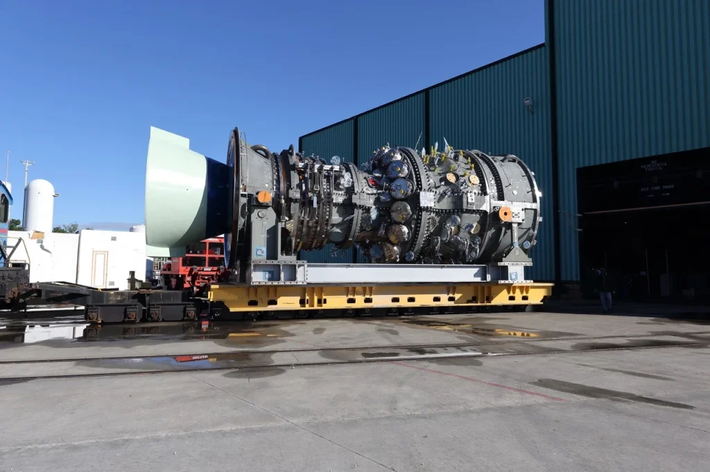
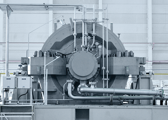
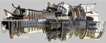
FOUNDATIONS – GAS TURBINES

FOUNDATIONS - GAS TURBINES
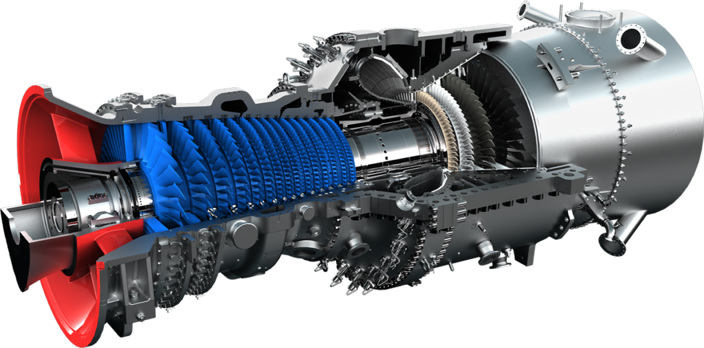
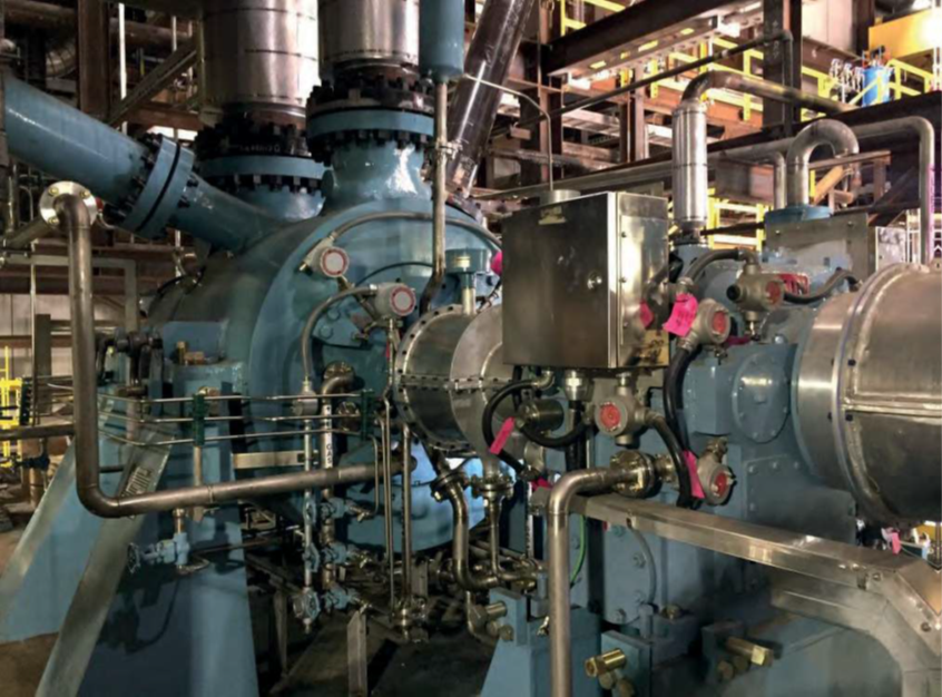
LIMITATIONS IN ENGINEERING & DESIGN - FOUNDATIONS

When it comes to the engineering and design of foundations for industrial gas turbines in power generation, oil, gas, and petrochemical industries, there are several limitations and critical risks that need to be considered to improve reliability, safety, and avoid critical failures in existing plants and new projects. These include:

  1. Soil Conditions: The foundation’s performance heavily relies on the underlying soil conditions. If the soil lacks sufficient bearing capacity, stability, or contains expansive soils, it can lead to settlement, differential movement, or even foundation failure. Understanding the soil characteristics through comprehensive geotechnical investigations is crucial.

  2. Vibration and Dynamic Loads: Gas turbines generate significant vibration and dynamic loads during operation. These loads can impose high stresses on the foundation, leading to fatigue and structural failure if not properly addressed. Vibration-induced issues can also propagate to other components, causing further damage and affecting the overall reliability of the turbine.

  3. Seismic Considerations: In regions prone to earthquakes, the foundation design must account for seismic forces. Failure to address seismic requirements adequately can result in catastrophic consequences during an earthquake event. Compliance with seismic codes and standards is crucial to ensure the safety and integrity of the foundation.

  4. Foundation Design and Structural Integrity: The foundation must be designed to support the weight of the gas turbine and withstand various operational and environmental loads, including wind loads and temperature differentials. Inadequate design, such as insufficient reinforcement or inadequate concrete strength, can lead to structural deficiencies and compromised reliability.

  5. Thermal Effects: Gas turbines experience significant temperature differentials during operation. The foundation design should consider the expansion and contraction of the turbine structure, as well as the associated thermal stresses. Failure to account for thermal effects can result in cracking, distortion, and potential failure of the foundation.

  6. Equipment Alignment: Proper alignment between the gas turbine and its foundation is crucial for the overall reliability and performance of the system. Misalignment can lead to increased vibrations, premature wear of components, and compromised safety. Strict alignment tolerances and careful installation procedures are essential.

  7. Accessibility and Maintainability: The foundation design should allow for easy access to critical components and facilitate maintenance activities. Limited accessibility can lead to challenges in inspections, repairs, and replacement of components, which can impact the reliability and safety of the gas turbine.

  8. Environmental Considerations: The foundation design should account for environmental factors such as soil erosion, water table level, corrosive environments, and exposure to chemicals or contaminants. Failure to address these factors can lead to deterioration, degradation, or accelerated corrosion of the foundation structure.

  9. Codes and Standards: Compliance with applicable codes and standards, such as those provided by industry organizations like ASCE, API, or turbine manufacturers’ recommendations, is crucial to ensure the foundation’s reliability, safety, and adherence to best practices.

Mitigating these limitations and critical risks requires thorough engineering analysis, adherence to best practices, collaboration between disciplines, and continuous monitoring and maintenance. By addressing these challenges and incorporating appropriate design considerations, the reliability and safety of gas turbine foundations can be enhanced, reducing the risks of critical failures in both existing plants and new projects in the power generation, oil, gas, and petrochemical industries.

WHY, WHEN, WHERE, WHAT, HOW TO APPLY ENGINEERING & DESIGN - FOUNDATIONS

Applying proper engineering and design principles to the foundations of industrial gas turbines is essential for improving reliability, safety, and avoiding critical failures and shutdowns in existing plants and new projects in the power generation, oil, gas, and petrochemical industries. Here’s a breakdown of why, when, where, what, and how to apply engineering and design considerations for gas turbine foundations:

  1. Why: Gas turbine foundations play a vital role in supporting the weight of the turbine and transmitting the generated loads to the ground. A well-designed foundation ensures stability, minimizes vibration and dynamic loads, and provides a safe and reliable operational environment for the gas turbine.

  2. When: Engineering and design considerations for gas turbine foundations should be applied during the initial stages of a project, including feasibility studies, conceptual design, and detailed engineering. They should also be considered during upgrades or modifications to existing gas turbine systems.

  3. Where: Gas turbine foundations are primarily used in power generation plants, oil refineries, gas processing facilities, and petrochemical plants. These foundations are typically designed for outdoor installations, although indoor installations may also be applicable in certain cases.

  4. What: Key aspects to consider in the engineering and design of gas turbine foundations include:

    • Site-specific geotechnical investigations to understand soil conditions, bearing capacity, and potential challenges.
    • Structural analysis and design to ensure the foundation can withstand static, dynamic, and seismic loads.
    • Vibration analysis and mitigation to minimize excessive vibrations and ensure the integrity of the foundation and surrounding structures.
    • Thermal expansion and contraction considerations to accommodate temperature differentials during turbine operation.
    • Alignment studies and precision installation to ensure proper alignment between the turbine and foundation.
    • Accessibility and maintainability features to allow for easy inspection, maintenance, and repairs.
    • Compliance with relevant codes, standards, and industry best practices.
  5. How: The engineering and design process for gas turbine foundations typically involves the following steps:

    • Conducting geotechnical investigations to understand soil properties, including bearing capacity, settlement characteristics, and seismicity.
    • Performing structural analysis and design to determine foundation size, reinforcement requirements, and structural integrity.
    • Utilizing advanced modeling and simulation techniques to evaluate the dynamic behavior of the foundation under operational loads.
    • Considering environmental factors, such as corrosive environments, water table level, and soil erosion, in the design process.
    • Collaborating with geotechnical engineers, structural engineers, turbine manufacturers, and construction professionals to ensure an integrated design approach.
    • Incorporating site-specific conditions and project requirements into the design, such as local regulations, environmental impact assessments, and safety standards.
    • Regular monitoring and inspection of the foundation during and after construction to verify performance and identify any maintenance or repair needs.

By applying these engineering and design practices, gas turbine foundations can be optimized for reliability, safety, and avoidance of critical failures and shutdowns. It is important to involve experienced professionals, follow industry guidelines, and conduct thorough assessments to ensure the foundation’s performance aligns with the specific requirements of the power generation, oil, gas, and petrochemical industries.
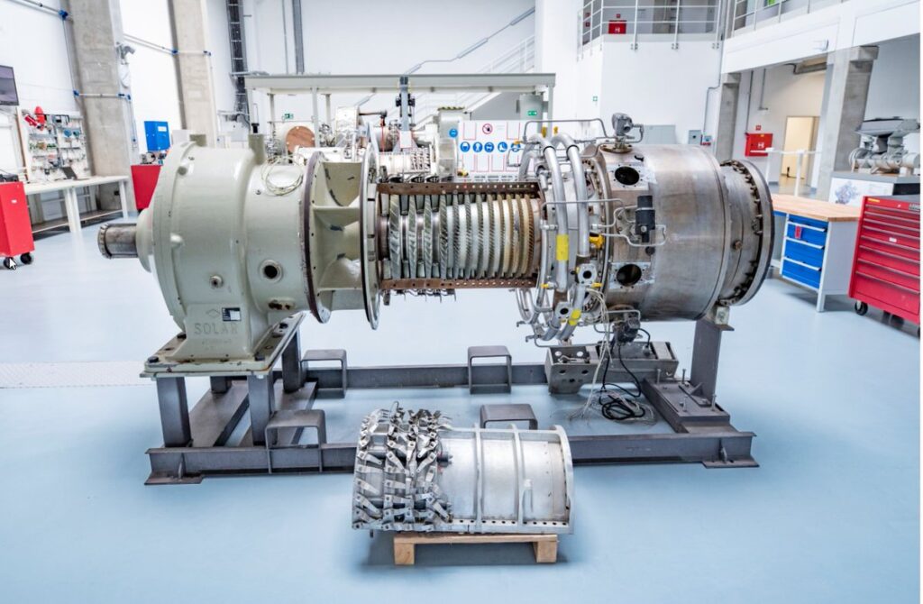
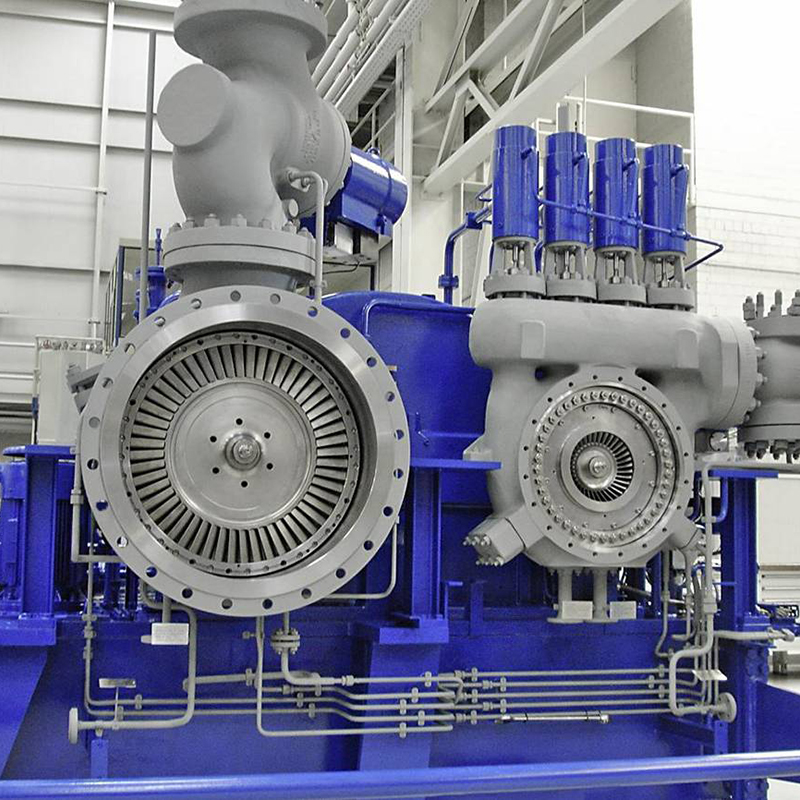
PROCEDURES, ACTIONS, STUDIES, MITIGATION, RECOMMENDATIONS IN ENGINEERING & DESIGN - FOUNDATIONS

To improve the reliability and safety of gas turbine foundations and avoid critical failures and shutdowns in existing plants and new projects in the power generation, oil, gas, and petrochemical industries, several procedures, actions, studies, mitigations, and recommendations can be applied. Here are some key considerations:

  1. Geotechnical Investigations:

    • Conduct comprehensive site-specific geotechnical investigations to assess soil properties, bearing capacity, and potential challenges.
    • Perform soil testing, including soil borings, laboratory tests, and geophysical surveys, to gather accurate data for foundation design.
  2. Structural Analysis and Design:

    • Engage experienced structural engineers to analyze loads, vibrations, and dynamic behavior of the gas turbine foundation.
    • Employ advanced structural analysis techniques, such as finite element analysis, to determine the optimal design for the foundation.
    • Consider factors like wind loads, seismic activity, and thermal expansion to ensure structural integrity.
  3. Vibration Analysis and Mitigation:

    • Conduct vibration analysis studies to identify potential resonance issues and mitigate excessive vibrations.
    • Use vibration isolation techniques, such as vibration isolators and dampers, to minimize vibrations transmitted to the foundation.
    • Consider the effects of nearby equipment and structures on the foundation’s dynamic response.
  4. Foundation Materials and Construction:

    • Select suitable foundation materials, such as reinforced concrete or steel, based on project requirements and site conditions.
    • Ensure proper construction techniques and quality control measures during foundation installation.
    • Monitor and control curing processes to achieve desired strength and durability.
  5. Environmental Considerations:

    • Evaluate environmental factors, such as corrosive atmospheres, high humidity, and temperature variations, and incorporate appropriate protective measures in the foundation design.
    • Consider potential impacts of water table level, soil erosion, and flood zones on the foundation’s stability and performance.
  6. Alignment and Precision Installation:

    • Ensure accurate alignment of the gas turbine and foundation to minimize operational issues and stress concentrations.
    • Utilize precision installation techniques, such as laser alignment, to achieve proper alignment and reduce mechanical stresses.
  7. Compliance with Codes and Standards:

    • Adhere to relevant industry codes, standards, and regulations, such as those issued by the American Society of Mechanical Engineers (ASME) and the International Building Code (IBC).
    • Stay updated with the latest revisions and requirements of applicable codes and standards.
  8. Monitoring and Maintenance:

    • Implement a comprehensive monitoring system to continuously assess the performance of the gas turbine foundation.
    • Regularly inspect and maintain the foundation, including visual inspections, non-destructive testing, and repairs if necessary.
    • Develop a maintenance plan that includes periodic inspections, foundation strengthening measures, and remedial actions.
  9. Collaboration and Expertise:

    • Foster collaboration among multidisciplinary teams, including geotechnical engineers, structural engineers, turbine manufacturers, and construction professionals.
    • Seek the expertise of experienced professionals and consultants with a strong background in gas turbine foundation design.

By following these procedures, taking appropriate actions, conducting necessary studies, implementing mitigations, and adhering to recommended practices, gas turbine foundation reliability and safety can be improved, critical failures and shutdowns can be avoided, and the performance of existing plants and new projects in the power generation, oil, gas, and petrochemical industries can be enhanced.
FOUNDATIONS – GAS TURBINES Leer más »

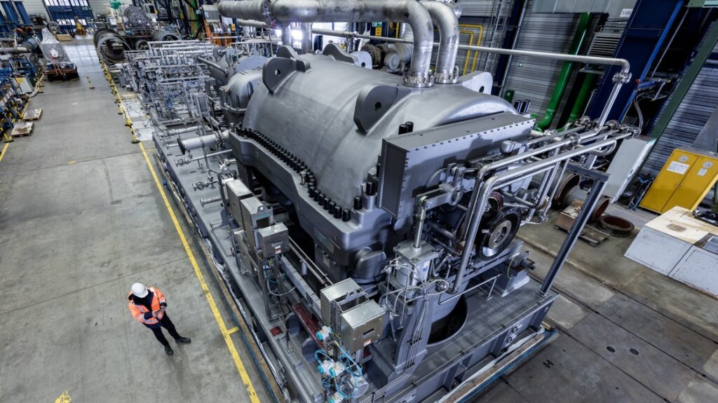
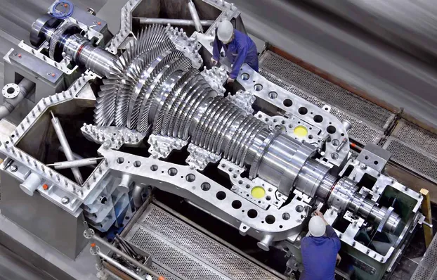
Consulting – CENTRIFUGAL COMPRESSORS – NON INTEGRALLY GEARED vs INTEGRALLY GEARED

CENTRIFUGAL COMPRESSORS - NON INTEGRALLY GEARED vs INTEGRALLY GEARED

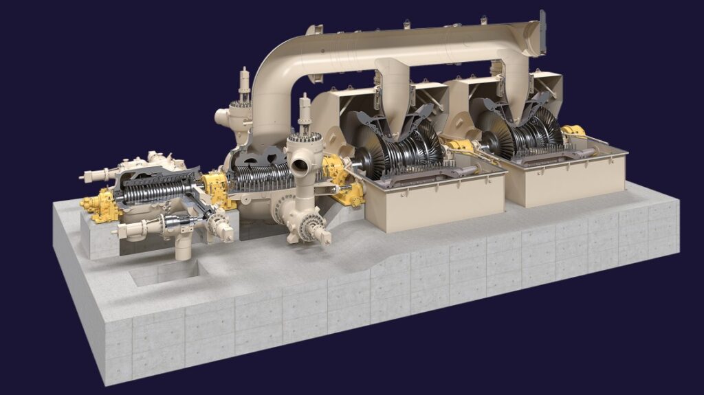
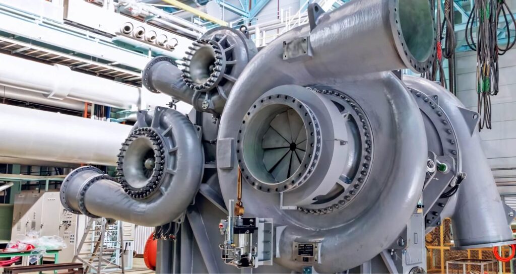
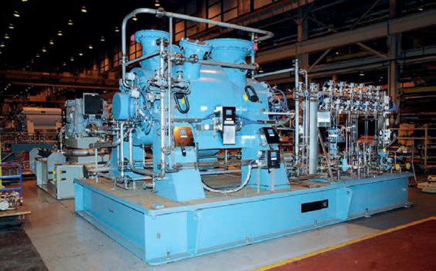
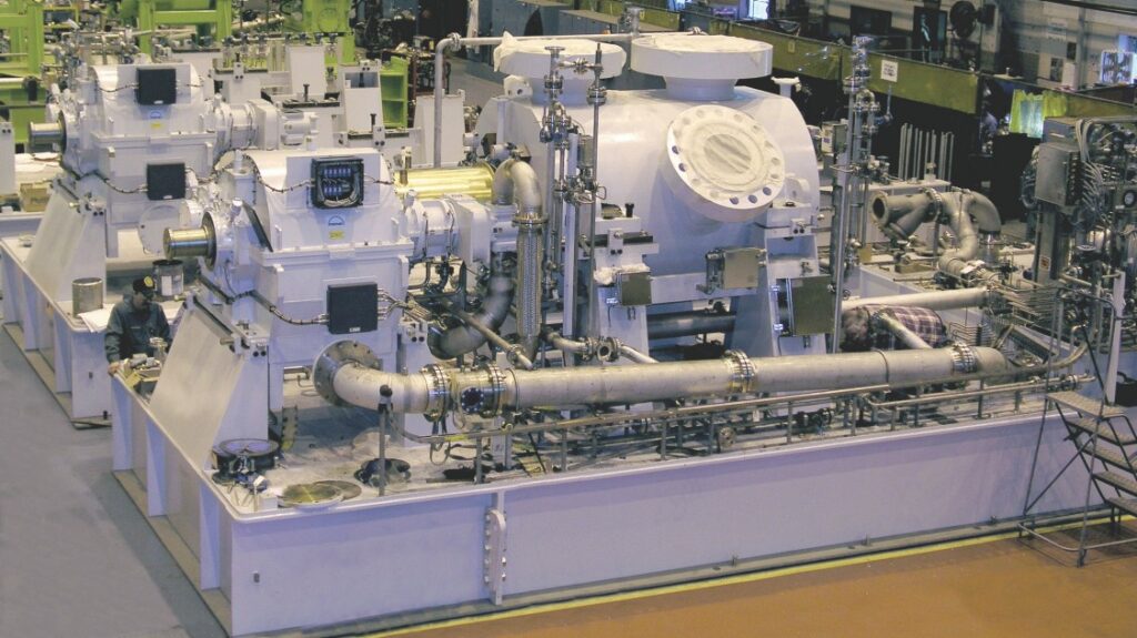
courtesy by KOBELCO

ADVANTAGES & DISADVANTAGES - NON INTEGRALLY GEARED vs INTEGRALLY GEARED

Centrifugal compressors are widely used in industrial plants in the oil, gas, and petrochemical industries for various applications. They can be classified as non-integrally geared or integrally geared based on their design. Here are the differences, advantages, and disadvantages of each type:

  1. Non-Integrally Geared Centrifugal Compressors:

    • Design: Non-integrally geared centrifugal compressors have a single impeller directly connected to the driver (typically an electric motor or a gas turbine).
    • Advantages:
      • Simplicity: Non-integrally geared compressors have a simpler design with fewer rotating parts, making them easier to operate and maintain.
      • Lower Cost: They generally have lower initial capital costs compared to integrally geared compressors.
      • Compact Size: Non-integrally geared compressors are usually more compact and require less space.
    • Disadvantages:
      • Limited Operating Range: Non-integrally geared compressors have a narrower operating range, making them less flexible in handling varying flow rates and pressures.
      • Lower Efficiency: They tend to have slightly lower efficiency compared to integrally geared compressors, especially at part-load conditions.
  2. Integrally Geared Centrifugal Compressors:

    • Design: Integrally geared centrifugal compressors have multiple impellers arranged in series and connected by a gearbox.
    • Advantages:
      • Wide Operating Range: Integrally geared compressors can handle a broader range of flow rates and pressures, making them suitable for applications with varying process conditions.
      • High Efficiency: They offer higher efficiency, especially at part-load conditions, due to the ability to optimize impeller speeds with the gearbox.
      • Improved Reliability: The gearbox allows for better load distribution and reduced stresses on the impellers, resulting in improved reliability and longer service life.
    • Disadvantages:
      • Higher Cost: Integrally geared compressors generally have higher initial capital costs due to the complexity of the gearbox.
      • Larger Size: They require more space compared to non-integrally geared compressors.
      • Increased Maintenance: The gearbox requires regular maintenance, including lubrication and inspection, adding to the maintenance requirements.

When to Use:

  • Non-Integrally Geared Compressors: These compressors are suitable for applications with a relatively constant operating point, where simplicity and lower capital cost are priorities.
  • Integrally Geared Compressors: They are preferred for applications with varying operating conditions, where higher efficiency, wider operating range, and improved reliability are critical.

Where to Use:

  • Both types of compressors are used in various applications within the oil, gas, and petrochemical industries, including gas processing, refining, petrochemical plants, and pipeline compression stations.

The selection between non-integrally geared and integrally geared compressors depends on factors such as process requirements, operating conditions, budget, and reliability considerations. A thorough analysis of the specific application, including flow rates, pressure ratios, turndown requirements, and lifecycle costs, is essential in determining the most suitable compressor type for a particular project or existing plant. Consulting with experienced compressor manufacturers and engineering consultants can provide valuable insights and guidance in making the appropriate selection.

LIMITATIONS IN ENGINEERING & DESIGN - NON INTEGRALLY GEARED vs INTEGRALLY GEARED

When considering the limitations in engineering and design of centrifugal compressors, both non-integrally geared and integrally geared compressors have certain factors that need to be taken into account. These limitations can impact the reliability, avoidance of critical failures, and environmental impacts in both existing plants and new projects in the oil, gas, and petrochemical industries. Here are some key limitations to consider:

  1. Non-Integrally Geared Centrifugal Compressors:

    • Limited Operating Range: Non-integrally geared compressors typically have a more limited operating range compared to integrally geared compressors. They may have challenges handling varying flow rates and pressures efficiently.
    • Turndown Ratio: Non-integrally geared compressors may have limitations in achieving a high turndown ratio, which is the ability to adjust the flow rate over a wide range. This can affect flexibility in meeting changing process demands.
    • Lower Efficiency at Part-Load: Non-integrally geared compressors may exhibit lower efficiency at part-load conditions compared to integrally geared compressors. This can result in higher energy consumption and environmental impacts.
  2. Integrally Geared Centrifugal Compressors:

    • Complexity and Cost: Integrally geared compressors are generally more complex in design, particularly due to the inclusion of a gearbox. This complexity can lead to higher initial capital costs, increased maintenance requirements, and potentially more complex troubleshooting.
    • Space Requirement: Integrally geared compressors tend to require more space compared to non-integrally geared compressors due to the inclusion of a gearbox.
    • Gearbox Reliability: The presence of a gearbox introduces an additional component that requires careful engineering and maintenance. The reliability of the gearbox is critical for the overall reliability of the compressor system.

To address these limitations and improve the reliability, avoidance of critical failures, and environmental impacts, it is essential to consider the following measures:

  1. Robust Design and Engineering:

    • Conduct a thorough analysis of the process requirements and operating conditions to select the appropriate compressor type (non-integrally geared or integrally geared) that aligns with the specific project needs.
    • Implement advanced engineering techniques, such as computational fluid dynamics (CFD) and finite element analysis (FEA), to optimize the design and performance of the compressor system.
    • Ensure compliance with relevant industry standards and codes to enhance safety and reliability.
  2. Proper Maintenance and Monitoring:

    • Implement a comprehensive maintenance program that includes regular inspections, lubrication, and condition monitoring of critical components, including the gearbox for integrally geared compressors.
    • Utilize advanced monitoring systems, such as vibration analysis and performance monitoring, to detect any potential issues and address them proactively.
  3. Adequate Training and Competence:

    • Ensure that personnel involved in the operation, maintenance, and troubleshooting of centrifugal compressors receive proper training and possess the necessary competence.
    • Establish clear procedures and protocols for operation, maintenance, and emergency shutdowns to minimize risks and ensure efficient and safe operations.

By considering these factors and implementing appropriate engineering and maintenance practices, the limitations associated with centrifugal compressors, whether non-integrally geared or integrally geared, can be effectively managed. This leads to improved reliability, avoidance of critical failures, reduced environmental impacts, and increased overall performance in both existing plants and new projects.

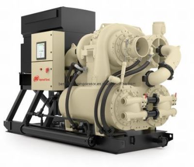
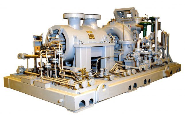
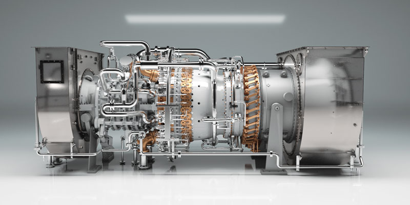
courtesy by INGERSOLL RAND

WHY, WHEN, WHERE, WHAT & HOW TO APPLY NON INTEGRALLY GEARED vs INTEGRALLY GEARED

To effectively apply centrifugal compressors, whether non-integrally geared or integrally geared, in industrial plants in the oil, gas, and petrochemical industries, with the aim of improving reliability, avoiding critical failures and risks, and minimizing environmental impacts, the following considerations should be taken into account:

  1. WHY:

    • Reliability Improvement: Both non-integrally geared and integrally geared centrifugal compressors can contribute to improved reliability by employing robust designs, proper maintenance practices, and monitoring systems.
    • Critical Failure Avoidance: Centrifugal compressors play a vital role in many industrial processes. By selecting the appropriate type and implementing suitable maintenance strategies, the risk of critical failures can be minimized.
    • Environmental Impact Reduction: Proper compressor selection, design optimization, and energy-efficient operation contribute to reducing the environmental footprint of the plant, including energy consumption and greenhouse gas emissions.
  2. WHEN:

    • New Projects: The selection of centrifugal compressors should be made during the design phase of a new plant or facility. Consideration should be given to the process requirements, operating conditions, turndown ratio, and energy efficiency goals.
    • Existing Plants: Upgrading or retrofitting existing plants with more efficient or reliable centrifugal compressors can be considered when aiming to improve overall system performance and reduce risks.
  3. WHERE:

    • Centrifugal compressors are widely used in various applications within the oil, gas, and petrochemical industries, including gas processing, refining, petrochemical plants, and pipeline compression stations.
  4. WHAT:

    • Selection of Compressor Type: Evaluate the specific requirements of the application, such as flow rates, pressure ratios, turndown requirements, and efficiency goals, to determine whether a non-integrally geared or integrally geared compressor is more suitable.
    • Design Optimization: Employ engineering techniques, such as computational fluid dynamics (CFD) and finite element analysis (FEA), to optimize the design and performance of the compressor system.
    • Maintenance Strategies: Implement a comprehensive maintenance program that includes regular inspections, lubrication, and condition monitoring of critical components, ensuring proper maintenance of both the compressor and associated systems.
  5. HOW:

    • Collaborate with experienced compressor manufacturers and engineering consultants who can provide expertise in compressor selection, design optimization, and maintenance strategies.
    • Adhere to industry standards, codes, and regulations to ensure compliance, safety, and reliability.
    • Continuously monitor and evaluate system performance, making necessary adjustments and improvements to enhance reliability and minimize risks.

By carefully considering these aspects and applying appropriate strategies, the use of centrifugal compressors, whether non-integrally geared or integrally geared, can lead to improved reliability, avoidance of critical failures and risks, reduced environmental impacts, and enhanced overall performance in both existing plants and new projects within the oil, gas, and petrochemical industries.

PROCEDURES, ACTIONS, STUDIES, MITIGATION, RECOMMENDATIONS TO APPLY - NON INTEGRALLY GEARED vs INTEGRALLY GEARED

To improve the reliability, avoid critical failures and risks, and minimize environmental impacts when using centrifugal compressors, both non-integrally geared and integrally geared, in industrial plants in the oil, gas, and petrochemical industries, the following procedures, actions, studies, mitigations, and recommendations can be implemented:

  1. Compressor Selection:

    • Conduct a thorough analysis of process requirements, including flow rates, pressure ratios, turndown requirements, and efficiency goals, to determine the most suitable compressor type (non-integrally geared or integrally geared) for the application.
    • Consider factors such as reliability, maintenance requirements, footprint, and overall system design when selecting a compressor.
  2. Engineering Design and Optimization:

    • Perform detailed engineering studies, such as computational fluid dynamics (CFD) simulations and finite element analysis (FEA), to optimize the design and performance of the compressor system.
    • Evaluate factors such as impeller design, volute configuration, sealing arrangements, and bearing systems to enhance reliability and efficiency.
    • Consider system integration and compatibility with other equipment and processes within the plant.
  3. Maintenance Strategies:

    • Develop a comprehensive maintenance program that includes regular inspections, lubrication, and condition monitoring of critical components.
    • Implement preventive maintenance actions, such as vibration analysis, oil analysis, and thermography, to detect early signs of potential failures.
    • Follow the manufacturer’s recommended maintenance practices and guidelines.
  4. Monitoring and Control Systems:

    • Install advanced monitoring and control systems to continuously monitor the performance and condition of the compressor.
    • Utilize real-time data and analytics to detect anomalies, predict failures, and optimize the operation of the compressor system.
    • Implement a remote monitoring system for off-site monitoring and diagnostics.
  5. Training and Competence:

    • Ensure that personnel involved in operating, maintaining, and troubleshooting the compressor system receive proper training and have the necessary competence.
    • Provide ongoing training to keep employees updated with the latest advancements in compressor technology, maintenance practices, and safety procedures.
  6. Mitigation of Environmental Impacts:

    • Optimize the compressor system for energy efficiency to minimize energy consumption and reduce carbon emissions.
    • Consider the use of variable frequency drives (VFDs) or speed control mechanisms to match the compressor output to the process demand, thereby reducing energy waste.
    • Implement noise reduction measures, such as acoustic enclosures or barriers, to mitigate noise pollution.
  7. Compliance and Safety:

    • Adhere to industry standards, codes, and regulations to ensure compliance and safety in the design, installation, and operation of the compressor system.
    • Conduct regular safety audits and risk assessments to identify potential hazards and implement necessary safety measures.
  8. Continuous Improvement:

    • Establish a culture of continuous improvement by conducting regular reviews and assessments of the compressor system’s performance.
    • Document and analyze any failures or incidents to identify root causes and implement corrective actions.
    • Stay updated with industry advancements and emerging technologies to identify opportunities for improvement.

By implementing these procedures, actions, studies, mitigations, and recommendations, industrial plants in the oil, gas, and petrochemical industries can enhance the reliability, mitigate critical failures and risks, minimize environmental impacts, and optimize the performance of centrifugal compressors, whether non-integrally geared or integrally geared, in both existing plants and new projects.

courtesy by ATLAS COPCO

Consulting – CENTRIFUGAL COMPRESSORS – NON INTEGRALLY GEARED vs INTEGRALLY GEARED Leer más »

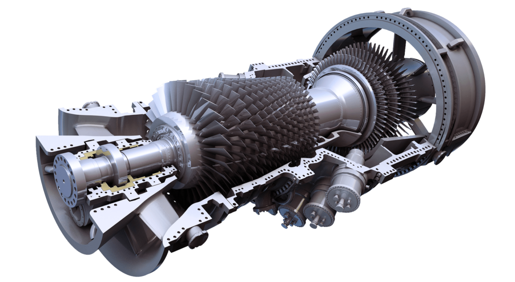
Consulting – RECOMMENDED PROCEDURES FOR INSTALLATION, COMMISSIONING, STARTUP & RELIABILITY TEST

RECOMMENDED PROCEDURES FOR INSTALLATION, COMMISSIONING, STARTUP & RELIABILITY TEST

CENTRIFUGAL COMPRESSORS

GAS TURBINES

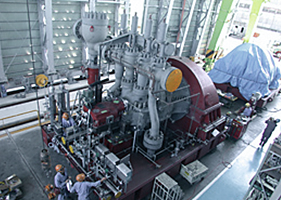
SPECIAL STEAM TURBINES

CENTRIFUGAL COMPRESSORS

The recommended procedures for the installation, commissioning, and start-up of centrifugal compressors are crucial to ensure their reliable operation, maintainability, and safety in oil, gas, and petrochemical industries. Here are some steps that can be taken:

  1. Installation: The installation process should be carried out by experienced personnel following the manufacturer’s recommendations and industry standards. The foundation, piping, and electrical connections must be designed and installed to meet the specified requirements.

  2. Commissioning: Before starting the compressor, all systems, components, and instrumentation should be checked and tested. The commissioning process includes checking the alignment of the compressor, verifying the proper operation of the control system and protective devices, and ensuring that all piping, valves, and instrumentation are functioning correctly.

  3. Start-up: The start-up process should be gradual, following the manufacturer’s recommended procedure. The operator must monitor the compressor’s operation during the start-up phase to detect any abnormal vibrations, noises, or temperatures.

  4. Reliability test: A reliability test for 72 continuous hours, scheduled two months after having gas available in the plant, can be performed to ensure that the compressor is operating at its rated capacity and efficiency. During the test, the performance parameters such as suction and discharge pressures, temperatures, and flow rates should be monitored and recorded. The results of the test can be used to verify the compressor’s performance, identify any issues, and make necessary adjustments.

  5. Regular maintenance: Regular maintenance activities such as cleaning, lubrication, and inspection should be carried out according to the manufacturer’s recommendations and industry standards. The maintenance activities should include checking the condition of the bearings, seals, and other components that are subject to wear and tear. The data obtained from the regular maintenance activities can be used to identify potential issues and prevent unscheduled shutdowns.

  6. Training and documentation: The operators and maintenance personnel should be trained on the proper operation and maintenance of the compressor. The documentation of the installation, commissioning, and maintenance activities should be properly recorded and updated to ensure that the compressor’s history is well-documented.

By following these recommended procedures, the installation, commissioning, and start-up of centrifugal compressors can be carried out safely, reliably, and efficiently, minimizing the risk of critical failures and unscheduled shutdowns in oil, gas, and petrochemical industries.

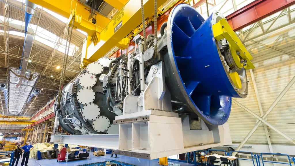
GAS TURBINES

The recommended procedures for installation, commissioning, and start-up of gas turbines in new projects and existing process plants are critical for ensuring reliable and safe operation and avoiding critical failures and unscheduled shutdowns. Here are some general steps that should be followed:

  1. Pre-installation and planning phase: This involves assessing the site conditions and requirements, selecting the appropriate turbine, designing the foundation and support systems, and identifying any special requirements or challenges.

  2. Mechanical installation phase: This involves preparing the site, installing and aligning the gas turbine, assembling the auxiliary systems, and conducting quality checks.

  3. Electrical and control installation phase: This involves installing and connecting the electrical and control systems, conducting cable and insulation tests, and performing functional tests.

  4. Commissioning and start-up phase: This involves checking and adjusting the operational parameters, testing the protection systems, and ensuring proper synchronization with the grid or process systems.

  5. Reliability test phase: This involves conducting a 72-hour continuous test after two months of having gas available in the plant, as specified in the question.

In addition to these general steps, there are several specific procedures and checks that should be followed during each phase to ensure that the gas turbine is installed, commissioned, and started up safely and reliably. These procedures and checks can vary depending on the specific gas turbine model and the site conditions, but some of the key considerations include:

  • Ensuring proper alignment and clearance of all components during mechanical installation.
  • Conducting vibration and noise measurements during mechanical and electrical installation.
  • Verifying the correct installation and connection of all electrical and control systems, including grounding and insulation checks.
  • Conducting functional tests of all systems, including fuel supply, oil supply, cooling systems, and fire protection systems.
  • Conducting a commissioning test run to check the overall performance and stability of the gas turbine.
  • Checking and adjusting the operational parameters, such as the fuel flow rate, temperature, and pressure, to ensure optimal performance and efficiency.
  • Verifying the proper functioning of all protection systems, including over-speed protection, temperature and pressure alarms, and emergency shutdown systems.
  • Conducting a reliability test after two months of having gas available in the plant, as specified in the question, to ensure that the gas turbine can operate continuously and reliably for extended periods.

Overall, following these recommended procedures for installation, commissioning, and start-up, including the reliability test, can help to ensure that gas turbines operate safely, reliably, and efficiently in power generation, oil, gas, and petrochemical industries.

SPECIAL STEAM TURBINES

The recommended procedures for installation, commissioning, and start-up of special steam turbines in new projects and existing process plants are critical to ensure their reliability, maintainability, and safety. Here are some general steps to consider:

  1. Transportation and handling: The steam turbine and its components should be transported and handled carefully to avoid any damage. The manufacturer’s instructions and best practices should be followed.

  2. Foundation: The steam turbine should be installed on a solid foundation designed to meet the manufacturer’s requirements, which should include an appropriate level of vibration isolation.

  3. Piping: Piping should be designed, installed, and tested to ensure proper alignment and minimum strain on the steam turbine. Valves and fittings should be installed according to the manufacturer’s instructions.

  4. Lubrication and control oil systems: These systems should be installed and tested according to the manufacturer’s instructions. Cleanliness is critical to ensure the reliability of the steam turbine.

  5. Instrumentation and control system: The instrumentation and control system should be installed and tested to ensure that the steam turbine operates safely and efficiently.

  6. Alignment: The steam turbine should be aligned to the manufacturer’s specifications to ensure that it operates smoothly and efficiently. Alignment should be checked before and after installation.

  7. Commissioning: After installation, the steam turbine should be commissioned in stages to ensure that it operates as intended. The commissioning process should include verifying the performance of the steam turbine under load.

  8. Reliability test: The reliability test should be conducted for 72 continuous hours, scheduled two months after the steam turbine has been installed and gas is available in the plant. The purpose of the test is to demonstrate the reliability of the steam turbine under continuous operation.

  9. Operation and maintenance: Once the steam turbine is in operation, it is important to follow the manufacturer’s recommendations for operation and maintenance to ensure its reliability and safety.

It is important to note that each steam turbine is unique, and the manufacturer’s instructions and best practices should be followed. Additionally, local regulations and standards should be considered when developing installation, commissioning, and start-up procedures.

FREQUENT QUESTIONS & ANSWERS

Here are some frequent questions and answers about the recommended procedures for installation, commissioning, and start-up of centrifugal compressors, gas turbines, and special steam turbines:

  1. What is the purpose of the reliability test for 72 continuous hours? Answer: The reliability test is performed to ensure that the turbine or compressor can operate continuously for a prolonged period without any failure or interruption. This test helps to identify any potential problems and correct them before the equipment is put into operation.

  2. Can the reliability test be skipped? Answer: It is not recommended to skip the reliability test as it is an essential part of the start-up process. Skipping the test can lead to unforeseen problems during operation, resulting in costly repairs and downtime.

  3. How can I ensure that the installation is done correctly? Answer: It is important to follow the manufacturer’s installation instructions and hire experienced and qualified personnel to handle the installation process. Proper alignment, foundation, and piping installation are critical for the smooth operation of the equipment.

  4. What are some common start-up issues with turbines and compressors? Answer: Some common start-up issues include inadequate lubrication, improper alignment, and incorrect operation of control systems. These issues can lead to equipment failure and downtime.

  5. What maintenance procedures should be followed after start-up? Answer: Regular maintenance procedures such as inspection, lubrication, and cleaning should be followed as per the manufacturer’s recommendations. Any abnormalities or problems should be addressed promptly to prevent unscheduled downtime and critical failures.

  6. Can I use different installation procedures for different types of turbines and compressors? Answer: Each type of turbine and compressor has unique installation, commissioning, and start-up procedures. It is important to follow the manufacturer’s recommendations for each type of equipment to ensure safe and reliable operation.

  7. What training is required for personnel involved in the installation and start-up of turbines and compressors? Answer: Personnel involved in the installation, commissioning, and start-up of turbines and compressors should have adequate training and experience to handle the equipment. This includes knowledge of safety procedures, installation techniques, and operation of control systems.

Consulting – RECOMMENDED PROCEDURES FOR INSTALLATION, COMMISSIONING, STARTUP & RELIABILITY TEST Leer más »

Consulting – PERFORMANCE TEST (AT SHOP vs AT SITE)

PERFORMACE TEST (AT SHOP vs AT SITE) - TURBOMACHINERY

CENTRIFUGAL COMPRESSORS

GAS TURBINES

SPECIAL STEAM TURBINES

FREQUENT QUESTIONS & ANSWERS ABOUT PERFORMANCE TEST

CENTRIFUGAL COMPRESSORS

Here are some frequently asked questions and answers regarding performance testing of centrifugal compressors:

Q: What is a performance test for centrifugal compressors? A: A performance test is a type of test conducted on a centrifugal compressor to evaluate its performance in terms of efficiency, capacity, power consumption, and other parameters.

Q: Why is a performance test necessary for centrifugal compressors? A: A performance test is necessary to ensure that the centrifugal compressor is operating efficiently, safely, and at its design capacity. It can also help identify any potential issues or inefficiencies that could lead to critical risks and failures.

Q: When should a performance test be conducted for a centrifugal compressor? A: A performance test should be conducted during the commissioning stage of a new centrifugal compressor or when the compressor undergoes major repairs or modifications. It is also recommended to conduct regular performance tests to ensure ongoing efficiency and reliability.

Q: What standards are used for performance testing of centrifugal compressors? A: The most commonly used standard for performance testing of centrifugal compressors is ASME PTC-10. Other standards may be used depending on the specific application and industry.

Q: Where should a performance test be conducted for a centrifugal compressor, at the shop or at the site? A: The decision to conduct a performance test at the shop or at the site depends on various factors such as the size of the compressor, accessibility, and availability of testing facilities. Site tests are typically preferred as they provide a more accurate representation of real-world operating conditions.

Q: How long does a performance test take? A: The duration of a performance test depends on various factors such as the size of the compressor and the parameters being tested. Typically, a performance test can take anywhere from a few hours to several days.

Q: What are some benefits of conducting a performance test for a centrifugal compressor? A: Some benefits of conducting a performance test include identifying potential issues before they become critical, improving efficiency and reliability, reducing downtime and maintenance costs, and ensuring compliance with industry standards and regulations.

GAS TURBINES

Here are some common questions and answers related to performance testing of gas turbines:

Q: What is the purpose of a performance test for gas turbines? A: The main purpose of a performance test for gas turbines is to verify their operational efficiency and to identify any performance deviations or issues that could lead to equipment failures or safety hazards. It is also used to ensure compliance with regulatory standards and to optimize operational costs.

Q: When is it necessary to perform a performance test for gas turbines? A: A performance test is typically conducted during the commissioning of a new gas turbine or after a major overhaul or repair work. It may also be performed periodically to monitor the performance and efficiency of the turbine, or if there are any significant changes in the operating conditions.

Q: What are the benefits of conducting a performance test at a shop rather than on-site? A: Conducting a performance test at a shop allows for greater control over the testing environment, reducing the potential for external factors to affect the results. Additionally, it can minimize downtime for the equipment being tested and reduce disruptions to the overall process plant operations.

Q: What are the benefits of conducting a performance test on-site rather than at a shop? A: Conducting a performance test on-site allows for a more accurate representation of the actual operating conditions, including variables such as ambient temperature and humidity, gas quality, and inlet pressure. It also allows for easier access to the equipment being tested, which can facilitate troubleshooting and identification of any issues that may arise.

Q: What standards are typically used for performance testing of gas turbines? A: The ASME PTC-22 standard is commonly used for performance testing of gas turbines, along with other international standards such as ISO 2314 and API 616.

Q: How long does a performance test for a gas turbine typically take? A: The duration of a performance test can vary depending on the specific equipment being tested and the testing procedures used. Generally, a full-scale performance test can take anywhere from several days to several weeks to complete.

Q: What are the potential risks or drawbacks of conducting a performance test for a gas turbine? A: There are some potential risks associated with performance testing, including the potential for equipment damage or failure during testing, and the possibility of measurement errors or inaccuracies. Additionally, performance testing can be costly and time-consuming, and may require significant planning and coordination with other plant operations.

SPECIAL STEAM TURBINES

Here are some frequently asked questions and answers regarding performance testing for special steam turbines:

Q: What is a special steam turbine? A: A special steam turbine is a type of turbine that is designed for a specific application or function, such as driving a pump or compressor in an industrial process.

Q: Why is performance testing important for special steam turbines? A: Performance testing is important for special steam turbines because it allows for the identification of any inefficiencies or malfunctions that may be affecting the turbine’s performance. By detecting these issues early, they can be addressed before they lead to more serious problems, such as equipment failure or safety hazards.

Q: What is the difference between testing at a shop and testing at a site? A: Testing at a shop involves conducting the performance test on the turbine while it is in a controlled environment, such as a manufacturing facility. Testing at a site involves conducting the test on the turbine while it is installed and operating in its intended location. Testing at a site allows for a more accurate assessment of the turbine’s performance under real-world conditions.

Q: What is ASME PTC-6? A: ASME PTC-6 is a performance testing standard developed by the American Society of Mechanical Engineers (ASME) for steam turbines. It provides guidelines for conducting performance tests and evaluating the results.

Q: What are some of the benefits of performance testing for special steam turbines? A: Some of the benefits of performance testing for special steam turbines include:

  • Improved efficiency and energy savings
  • Identification of issues that could lead to equipment failure or safety hazards
  • Verification of the turbine’s design specifications
  • Optimization of maintenance and repair schedules
  • Improved overall reliability and performance of the turbine.

Consulting – PERFORMANCE TEST (AT SHOP vs AT SITE) Leer más »

Consulting – OREDA STUDIES (OFFSHORE & ONSHORE RELIABILITY DATA) – TURBOMACHINERY

OREDA STUDIES (OFFSHORE & ONSHORE RELIABILITY DATA) - TURBOMACHINERY

CENTRIFUGAL COMPRESSORS

GAS TURBINES

SPECIAL STEAM TURBINES

HISTORY ABOUT OREDA

LIMITATIONS IN DATA ADQUISITION

OREDA (Offshore/Onshore Reliability Data) was established in the late 1970s as a joint industry project aimed at collecting and sharing reliability data for offshore oil and gas facilities. The first edition of the OREDA handbook was published in 1981, and it contained reliability data for various types of equipment, including turbomachinery like centrifugal compressors, gas turbines, and steam turbines.

Since then, OREDA has undergone several phases of evolution. The second edition of the handbook was published in 1987, and it included data for additional equipment types, such as reciprocating compressors and pumps. In the 1990s, OREDA expanded its scope to include onshore facilities as well, and the third edition of the handbook was published in 1996.

In the early 2000s, OREDA began to focus on more advanced techniques for reliability data analysis, including Bayesian updating and fault tree analysis. The fourth edition of the handbook, published in 2002, included updated data for existing equipment types as well as new data for subsea equipment and offshore structures.

In the following years, OREDA continued to refine its methods and expand its scope, with the fifth edition of the handbook published in 2015. This edition included updated data for all equipment types, as well as new data for offshore wind turbines and other renewable energy systems.

Throughout its history, OREDA has focused on improving the reliability, maintainability, availability, and safety of equipment in the oil and gas industry. The data collected and analyzed by OREDA is used by equipment manufacturers, operators, and regulators to identify potential failure modes and develop strategies to mitigate those risks. The maintenance repair time data collected by OREDA is also used to inform maintenance scheduling and optimize maintenance practices, reducing downtime and improving overall equipment performance.

While OREDA (Offshore and Onshore Reliability Data) provides valuable information on the reliability and performance of machinery in the oil, gas, and petrochemical industries, there are several limitations to consider:

  1. Participation: OREDA relies on participation from companies in the industry to collect data on equipment failures and maintenance practices. However, not all companies participate, which can result in gaps in the data and potentially biased results.

  2. Data Quality: The reliability of the OREDA data is dependent on the quality and accuracy of the data provided by the participating companies. Incomplete or inaccurate data can lead to incorrect conclusions and recommendations.

  3. Scope: The OREDA handbooks provide information on a wide range of equipment and failure modes, but they may not cover all possible failure modes or equipment types. For example, the handbooks may not cover newer equipment technologies or specialized equipment used in specific applications.

  4. Applicability: While the OREDA handbooks provide guidance on the failure modes and maintenance practices associated with centrifugal compressors, the applicability of this information to specific compressor designs and operating conditions may vary.

  5. Maintenance Time: OREDA provides valuable information on best practices for maintenance and monitoring of machinery, but the time required for maintenance can be a significant constraint in some operating environments. For example, offshore platforms may have limited access to equipment and require maintenance to be completed quickly and efficiently.

Despite these limitations, the information provided by OREDA can still be a valuable resource for improving the reliability, maintainability, availability, and safety of machinery in the oil, gas, and petrochemical industries. However, it is important to consider the limitations and apply the information judiciously in the context of specific equipment designs and operating conditions.

FAILURE TYPES

FAILURE MODES - TURBOMACHINERY

OREDA (Offshore and Onshore Reliability Data) categorizes failures into three types: critical, degradation, and incipient.

  1. Critical Failures: These are failures that result in immediate and severe consequences, such as a catastrophic equipment failure or a safety incident. Critical failures can lead to significant downtime, production losses, and safety hazards.

  2. Degradation Failures: These are failures that occur gradually over time, as equipment components wear out or degrade due to environmental factors or normal wear and tear. Degradation failures can lead to reduced equipment performance, increased maintenance requirements, and reduced asset life.

  3. Incipient Failures: These are failures that have not yet caused equipment downtime or significant performance degradation, but which can potentially lead to more serious failures if left unaddressed. Incipient failures are often detected through condition monitoring techniques, such as vibration analysis, oil analysis, or visual inspections.

The OREDA handbooks provide information on the failure modes and mechanisms associated with each of these types of failures, as well as guidance on best practices for maintenance and monitoring to detect and prevent them. However, the time required for maintenance can be a significant constraint in some operating environments, and it is important to balance maintenance needs with operational requirements.

By understanding the different types of failures and their associated mechanisms, companies can prioritize their maintenance activities and optimize their maintenance schedules to reduce downtime, improve equipment reliability, and enhance safety in the oil, gas, and petrochemical industries.

The OREDA (Offshore and Onshore Reliability Data) handbooks provide information on the failure modes associated with centrifugal compressors, gas turbines, and steam turbines, as well as guidance on best practices for maintenance and monitoring to detect and prevent these failures. Some of the common failure modes for these types of machinery include:

  1. Centrifugal Compressors: Failure modes for centrifugal compressors include bearing failures, seal failures, rotor imbalance, corrosion, and erosion. The OREDA handbooks provide detailed information on the frequency and severity of these failure modes, as well as guidance on best practices for maintenance and monitoring to prevent them.

  2. Gas Turbines: Failure modes for gas turbines include blade and vane failures, combustor failures, bearing failures, and thermal fatigue. The OREDA handbooks provide information on the frequency and severity of these failure modes, as well as guidance on best practices for maintenance and monitoring to prevent them.

  3. Steam Turbines: Failure modes for steam turbines include blade and vane failures, rotor and shaft failures, bearing failures, and thermal fatigue. The OREDA handbooks provide information on the frequency and severity of these failure modes, as well as guidance on best practices for maintenance and monitoring to prevent them.

In addition to these failure modes, the OREDA handbooks also provide information on other factors that can impact the reliability, maintainability, availability, and safety of machinery, such as environmental factors, operational conditions, and maintenance practices. By understanding the specific failure modes and risk factors associated with their machinery, companies can prioritize their maintenance activities and optimize their maintenance schedules to reduce downtime, improve equipment reliability, and enhance safety in the oil, gas, and petrochemical industries. However, it is important to consider the time required for maintenance and repair, and balance maintenance needs with operational requirements.

LIST OF FAILURE MODES USED BY OREDA

LIST OF FAILURE MECHANISMS USED BY OREDA

OREDA defines a comprehensive list of failure modes for turbomachinery, including:

  1. Abnormal instrument reading: This refers to cases where instrument readings are outside the normal range, which could indicate an issue with the system being monitored. For example, abnormal temperature readings could indicate a problem with the cooling system.

  2. Breakdown: This refers to a sudden and catastrophic failure of a component or system, resulting in a shutdown of the equipment. This can be caused by a variety of factors, including material failure, poor maintenance, or unexpected loads.

  3. External leakages: This refers to leaks from external components, such as valves, pumps, or fittings. External leaks can lead to environmental damage, safety hazards, and loss of production.

  4. Erratic output: This refers to situations where the output of the equipment varies unexpectedly or is outside of the desired range. This can be caused by issues with control systems, instrumentation, or other components.

  5. Fail to start & to stop: This refers to issues with the equipment’s ability to start or stop when commanded. This can be caused by issues with control systems, fuel supply, or other components.

  6. High & low output: This refers to situations where the output of the equipment is either too high or too low. This can be caused by issues with control systems, instrumentation, or other components.

  7. Internal leakage: This refers to leaks from internal components, such as seals, bearings, or valves. Internal leaks can lead to reduced efficiency, increased wear and tear, and safety hazards.

  8. Noise: This refers to excessive noise or vibration from the equipment, which can indicate issues with components such as bearings, seals, or rotors.

  9. Overheating: This refers to situations where components or systems become too hot, which can cause damage to the equipment or create safety hazards.

  10. Parameter deviation: This refers to cases where critical parameters such as temperature, pressure, or flow rate deviate from the desired range. This can be caused by issues with instrumentation, control systems, or other components.

  11. Plugged/choked: This refers to situations where equipment components become plugged or choked with debris, which can lead to reduced efficiency, increased wear and tear, and safety hazards.

  12. Minor in-service problems: This refers to issues that may not result in a shutdown or significant downtime, but can still lead to reduced efficiency, increased wear and tear, or safety hazards.

  13. Structural deficiency: This refers to issues with the structural integrity of the equipment or supporting systems, such as cracks, corrosion, or fatigue.

  14. Spurious stop: This refers to cases where the equipment shuts down unexpectedly, without a clear cause. This can be caused by issues with control systems, instrumentation, or other components.

Each of these failure modes can be evaluated using data from OREDA studies, and appropriate mitigation strategies can be developed to improve reliability, maintainability, availability, and safety in turbomachinery.

list of failure mechanisms used by OREDA and a brief explanation of each:

  1. Blockage/Plugged: This refers to the obstruction of a flow path or channel, which could be caused by foreign objects, scale, or debris.

  2. Breakage: This occurs when a component fractures or cracks under the load, and can be caused by material defects or excessive stress.

  3. Burst: This refers to the sudden failure of a pressure-containing component, often due to overpressure or a material defect.

  4. Clearance/Alignment Failure: This refers to the failure of components to maintain the correct clearance or alignment, often caused by wear or deformation.

  5. Combined Causes: This refers to failures that are the result of multiple factors, such as a combination of wear and corrosion.

  6. Contamination: This refers to the introduction of foreign substances into a component or system, which can cause damage or fouling.

  7. Control Failure: This refers to the failure of control systems or components, which can lead to improper operation or damage to other components.

  8. Corrosion: This refers to the degradation of materials due to chemical reactions with the environment, such as the corrosion of metal components in a corrosive gas stream.

  9. Deformation: This refers to the change in shape or dimensions of a component or structure, which can be caused by excessive stress or temperature.

  10. Electrical Failure: This refers to the failure of electrical components or systems, such as motors or control circuits.

  11. External Influence: This refers to failures caused by external factors, such as weather events, operator error, or vandalism.

  12. Faulty Power/Voltage: This refers to failures caused by issues with the power supply or voltage level, such as under-voltage or over-voltage conditions.

  13. Faulty or No Signal/Indication/Alarm: This refers to failures caused by issues with the sensing, indication, or alarm systems, which can lead to improper operation or damage to other components.

  14. Instrument Failure: This refers to the failure of instruments used for measurement or control, such as pressure or temperature sensors.

  15. Leakage: This refers to the escape of fluids or gases from a component or system, which can lead to reduced performance or damage to other components.

  16. Looseness: This refers to the failure of components to remain securely fastened or attached, often caused by wear or vibration.

  17. Material Failure: This refers to the failure of materials due to factors such as fatigue, stress, or defects.

  18. Mechanical Failure: This refers to the failure of mechanical components or systems, such as bearings or gears.

  19. Miscellaneous: This category includes failures that do not fit into any other category, such as those caused by design errors or inadequate maintenance practices.

  20. Open Circuit: This refers to failures caused by an interruption in the electrical circuit, such as a broken wire or connection.

  21. Out of Adjustment: This refers to the failure of components or systems to maintain the correct settings or adjustments, often caused by wear or improper maintenance.

  22. Overheating: This refers to the increase in temperature of components or systems beyond the designed limits, often caused by excessive friction or insufficient cooling.

  23. Software Failure: This refers to failures caused by errors or bugs in software used for control or monitoring.

  24. Sticking: This refers to the failure of components to move or operate smoothly, often caused by wear, corrosion, or contamination.

  25. Vibration: This is a common failure mechanism in turbomachinery caused by the movement of rotating components. Excessive vibration can lead to fatigue failure of components, looseness of bolts and fasteners, and even catastrophic failure of the machine. The causes of vibration can be due to misalignment, imbalance, worn bearings, unbalanced loads, and even electrical or mechanical resonance. 

  26. Wear: Wear is a gradual process of material loss due to friction or erosion. It is a common failure mechanism in turbomachinery due to the high-speed rotation of components and exposure to high-temperature and high-pressure conditions. Wear can lead to reduced efficiency, decreased output, and increased risk of catastrophic failure. The causes of wear can be due to abrasive particles, corrosion, thermal expansion, or poor lubrication. 


Consulting – OREDA STUDIES (OFFSHORE & ONSHORE RELIABILITY DATA) – TURBOMACHINERY Leer más »

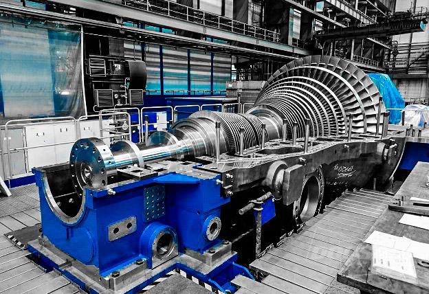
Consulting – ADVANCES IN TECHNOLOGY – SPECIAL STEAM TURBINES

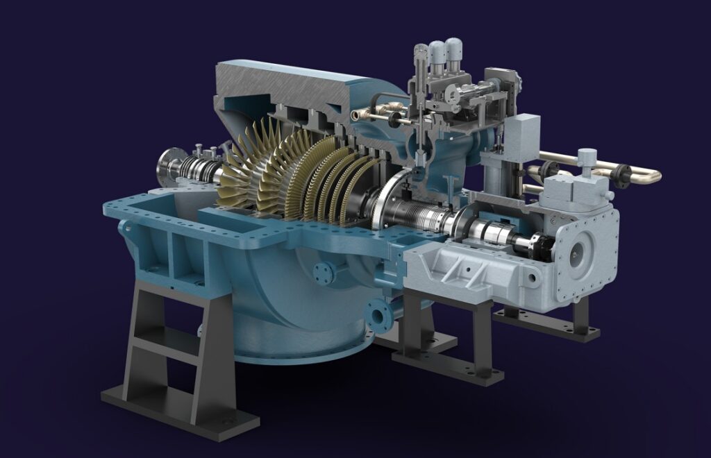
ADVANCES IN TECHNOLOGY - SPECIAL STEAM TURBINES

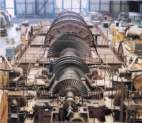
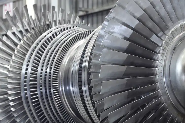
courtesy by MHI

DIFFERENCES - IMPULSE vs REACTION - SPECIAL STEAM TURBINES - APPLICABILITY

ROTODYNAMIC TECHNOLOGY FOR SPECIAL STEAM TURBINES

Reaction and impulse steam turbines are two types of steam turbines that have distinct design characteristics and are used for different applications in various industries, including power generation and oil and gas.

Impulse steam turbines are typically used in power generation plants and are designed to handle high-pressure and low-flow steam conditions. In an impulse turbine, the steam flows through a series of nozzles, which convert its pressure into kinetic energy, and then into mechanical energy through the turbine blades. The rotor of an impulse turbine is supported by bearings located at each end of the shaft.

Reaction steam turbines, on the other hand, are typically used in industries such as oil and gas, chemical, and petrochemical, and are designed to handle high-flow and low-pressure steam conditions. In a reaction turbine, the steam flows through a series of stationary blades (stator) and then through a series of rotating blades (rotor), which convert the steam’s pressure and velocity into mechanical energy. The rotor of a reaction turbine is typically supported by journal bearings, which allow for axial movement of the rotor.

In terms of applicability in power generation plants, impulse turbines are typically used in low-pressure and high-flow conditions, such as in a nuclear or fossil fuel power plant. Reaction turbines are used in high-pressure and low-flow conditions, such as in a hydroelectric power plant or in a combined cycle power plant. Reaction turbines are also commonly used in the oil and gas industry for power generation or to drive compressors or pumps.

In terms of environmental concerns, both impulse and reaction turbines can contribute to greenhouse gas emissions, as they typically rely on fossil fuels to generate the steam required for operation. However, modern designs and technologies, such as the use of renewable energy sources or carbon capture and storage, can help reduce the environmental impact of these turbines.

In terms of reliability, availability, and safety, both types of turbines must be designed and maintained to meet the specific requirements of their applications. Proper maintenance, including regular inspection and replacement of worn or damaged parts, is essential to ensure the safe and reliable operation of both impulse and reaction turbines. Additionally, appropriate safety measures must be in place to prevent critical failures and unscheduled shutdowns, which can result in equipment damage, injury, or even loss of life.

Overall, the choice between impulse and reaction turbines depends on the specific requirements of the application, including steam conditions, power output, and environmental considerations. Both types of turbines have their advantages and limitations, and proper engineering and design are critical to ensure their reliable and safe operation in power generation plants and in the oil and gas industry.

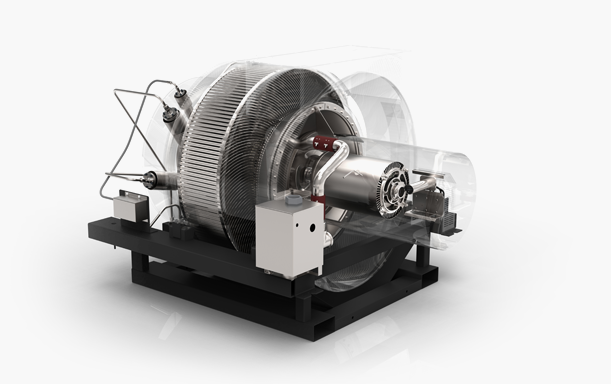
Rotodynamic technology is a field of engineering that deals with the analysis and design of rotating machinery such as turbines, compressors, and pumps. In the context of special steam turbines, rotodynamic technology plays a crucial role in improving their reliability and safety.

One of the key aspects of rotodynamic technology in special steam turbines is lateral analysis, which involves studying the lateral vibrations of the turbine shaft and bearings. This is important because excessive vibration can lead to mechanical failure and reduced turbine efficiency. Lateral analysis helps in identifying the critical speeds and modes of vibration that could potentially cause problems and allows for the selection of appropriate bearings and dampers to mitigate the risk.

Torsional analysis is another important aspect of rotodynamic technology in special steam turbines. It involves analyzing the torsional vibrations of the turbine shaft and is crucial in ensuring that the shaft remains stable and does not break due to fatigue. Torsional analysis helps in identifying the natural frequencies of the shaft and enables the design of appropriate torsional damping systems.

Stiffness-stability maps are also used in rotodynamic technology to optimize the design of special steam turbines. These maps are graphical representations of the relationship between the stiffness and stability of the rotor system. They help in identifying the most stable operating conditions for the turbine and enable the selection of appropriate bearing and damper configurations.

Resonance and structural issues are other important considerations in the design of special steam turbines. Resonance can occur when the natural frequency of the rotor system coincides with the operating frequency of the turbine, leading to excessive vibration and potential failure. Structural issues such as fatigue and cracking can also occur due to the cyclic loading of the turbine components. Mitigation measures such as careful material selection, appropriate design of the turbine components, and regular maintenance can help in avoiding such issues.

Overall, rotodynamic technology plays a critical role in improving the reliability, safety, and efficiency of special steam turbines in power generation plants and in the oil and gas industry.

LIMITS IN ENGINEERING & DESIGN - COMPARATIVE IMPULSE vs REACTION TYPE

LIMITS IN ENGINEERING & DESIGN OF ROTODYNAMIC TECHNOLOGY IN SPECIAL STEAM TURBINES

The selection of a steam turbine type for a specific application depends on various factors, including the characteristics of the steam, operating conditions, load requirements, and other specific needs of the application.

In terms of engineering and design limits, reaction turbines tend to be more complex and costly than impulse turbines due to the need for multiple stages and more precise tolerances. They are also more susceptible to vibration and require more frequent maintenance. Impulse turbines, on the other hand, have simpler designs and are less expensive to manufacture, but are less efficient at low-pressure ratios and cannot handle as much steam flow.

When it comes to power generation plants, both reaction and impulse turbines have their advantages and disadvantages. Reaction turbines are well-suited for large-scale power generation applications where high efficiency is critical, while impulse turbines are typically used for small-scale power generation applications or where low-pressure steam is available.

In the oil and gas industry, steam turbines are commonly used for applications such as oil and gas processing, pipeline compression, and steam injection for enhanced oil recovery. The choice of turbine type will depend on the specific needs of the application. Reaction turbines may be preferred for high-pressure steam applications such as pipeline compression, while impulse turbines may be more suitable for low-pressure steam applications.

Overall, the engineering and design limits of steam turbines, whether reaction or impulse type, depend on the specific needs of the application and the operating conditions. Proper selection, installation, and maintenance are critical to ensuring high reliability, availability, safety, and environmental performance while avoiding critical failures and unscheduled shutdowns.

The limits in engineering and design of rotodynamic technology being applicable in special steam turbines are important to consider in order to ensure high reliability, availability, safety, and avoid critical and environmental failures and unscheduled shutdowns in power generation plants and oil & gas industries.

One limit is the accuracy of the lateral analysis, which is used to determine the critical speeds and modes of the rotor system. If the lateral analysis is inaccurate, the rotor system may experience excessive vibrations, which can lead to premature failure of bearings and other components. Therefore, it is important to use accurate measurement and simulation techniques to ensure that the lateral analysis is reliable.

Another limit is the accuracy of the torsional analysis, which is used to determine the natural frequency and mode shapes of the rotor system in torsion. If the torsional analysis is inaccurate, the rotor system may experience torsional vibrations, which can lead to fatigue failure of shafts and other components. Therefore, it is important to use accurate measurement and simulation techniques to ensure that the torsional analysis is reliable.

The stiffness-stability map is another important consideration in the design of special steam turbines. This map shows the relationship between the stiffness of the rotor system and its stability, and helps to determine the optimal stiffness values for different operating conditions. If the stiffness-stability map is not properly designed, the rotor system may experience instability, which can lead to catastrophic failure of the turbine. Therefore, it is important to carefully design the stiffness-stability map based on accurate measurement and simulation techniques.

Resonance mechanical and structural issues are also important limits to consider in the design of special steam turbines. These issues can arise when the natural frequencies of the rotor system and the support structure are in resonance, leading to excessive vibrations and potential failures. Therefore, it is important to carefully design the rotor system and the support structure to avoid resonance conditions and ensure reliable operation.

In summary, the limits in engineering and design of rotodynamic technology being applicable in special steam turbines involve ensuring the accuracy of lateral and torsional analysis, designing an optimal stiffness-stability map, and avoiding resonance mechanical and structural issues. By carefully considering these limits, it is possible to improve the reliability and safety of special steam turbines in power generation plants and oil & gas industries.

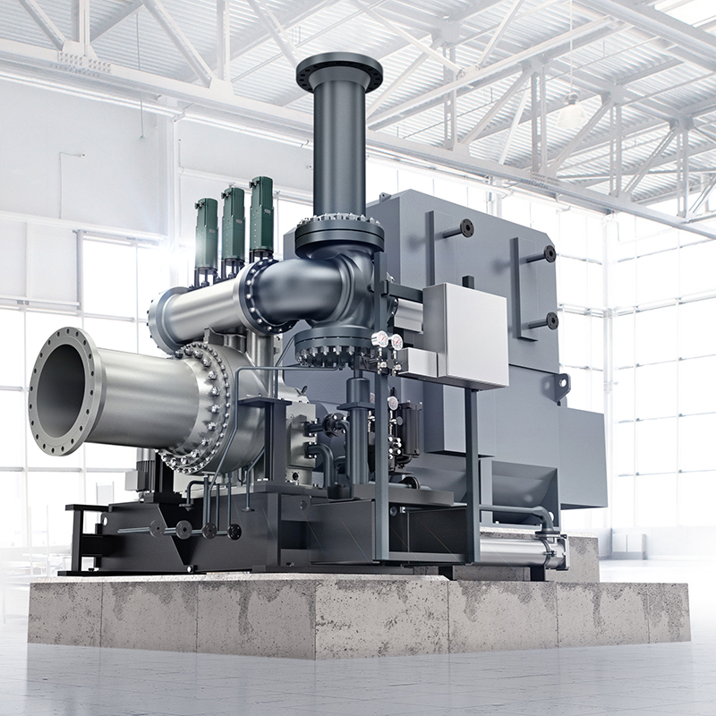
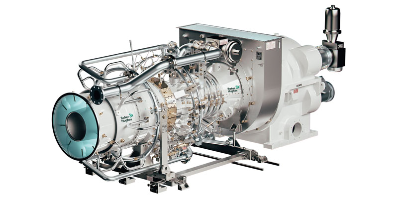
courtesy by BAKER HUGHES

CRITICAL RISKS AND FAILURES, AND PROCEDURES, ACTIONS, STUDIES, RECOMENDATIONS TO USE IMPULSE vs REACTION TYPE DESIGN

CRITICAL RISKS & FAILURES, PROCEDURES, ACTIONS, STUDIES, RECOMMENDATIONS IN ROTODYNAMIC TECHNOLOGY

The critical risks and failures associated with the use of special steam turbines, whether reaction or impulse type, in power generation plants and oil and gas industries include:

  1. Wear and tear: As with any machinery, steam turbines are subject to wear and tear, which can lead to component failures, power loss, and unscheduled downtime.

  2. Vibration: High levels of vibration can cause mechanical failures, such as fatigue and cracks in components, and can also cause damage to bearings and other parts of the turbine.

  3. Corrosion: Steam turbines are often exposed to harsh environments and high temperatures, which can cause corrosion and erosion of components.

  4. Water quality: The quality of the water used in the steam cycle can affect the reliability and efficiency of the turbine. Impurities in the water can cause corrosion and scaling, leading to reduced efficiency and power output.

To mitigate these risks and failures, procedures and actions can be taken such as:

  1. Regular maintenance: Regular maintenance, including inspections, cleaning, and replacement of worn or damaged parts, can help to prevent failures and prolong the life of the turbine.

  2. Monitoring: Regular monitoring of vibration levels, temperature, and other parameters can help to detect potential issues before they become critical.

  3. Water treatment: Proper water treatment, including filtration and chemical treatment, can help to prevent scaling, corrosion, and other water-related issues.

  4. Upgrades and modifications: Upgrading and modifying the turbine, such as adding sensors or improving the control system, can improve reliability and efficiency.

  5. Training and education: Providing training and education to the staff operating and maintaining the turbine can improve safety and reduce the risk of human error.

The limits in engineering and design when choosing between reaction and impulse type steam turbines depend on the specific application and operating conditions. For example, reaction turbines are better suited for high-pressure, high-flow applications, while impulse turbines are better suited for low-pressure, low-flow applications. The choice of turbine also depends on factors such as efficiency, cost, and maintenance requirements. It is important to carefully consider these factors when selecting a steam turbine for a particular application.

The critical risks and failures associated with the rotodynamic technology being applicable in special steam turbines mainly relate to mechanical and structural issues that can result in the failure of the turbine, unscheduled shutdowns, and potentially catastrophic accidents. Some of these risks and failures include:

  1. Lateral instability leading to vibration, which can cause damage to the turbine and other components in the system.
  2. Torsional instability leading to excessive twisting and potential damage to the turbine.
  3. Resonance, which can cause significant vibration and damage to the turbine and surrounding equipment.
  4. Structural issues, including material fatigue and creep, which can lead to catastrophic failures.

To mitigate these risks, procedures and actions need to be taken, including the following:

  1. Conducting thorough lateral and torsional analyses to ensure the turbine’s stability and avoid vibration issues.
  2. Developing stiffness-stability maps to ensure the turbine’s structural integrity and avoid resonance issues.
  3. Using advanced design and analysis tools to identify and address any potential mechanical and structural issues.
  4. Conducting regular inspections and maintenance to monitor the condition of the turbine and identify any potential issues before they become critical.
  5. Implementing appropriate safety protocols and emergency response plans to minimize the risk of accidents.

In addition to these mitigation measures, it is also essential to ensure that the turbine’s design is appropriate for the intended application and operating conditions. The limits in engineering and design need to be carefully considered, and any potential issues addressed during the design phase to ensure the turbine’s reliability, availability, and safety.

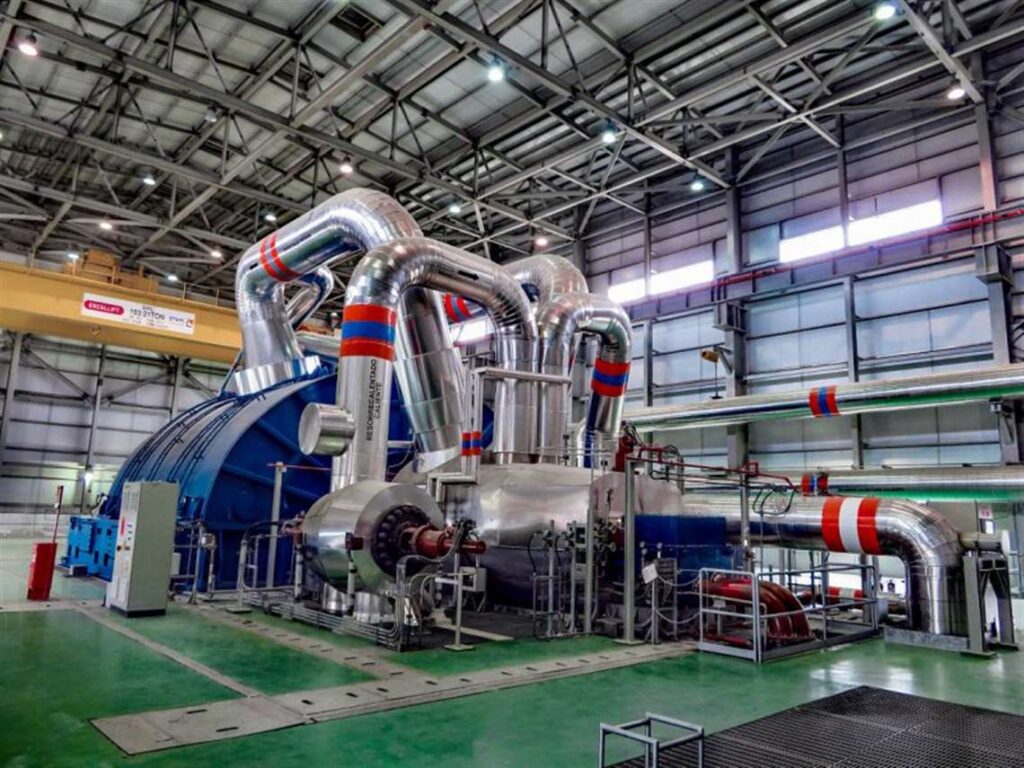
courtesy by SIEMENS

RERATES, UPGRADES, MODIFICATIONS IN DESIGN OF SPECIAL STEAM TURBINES

REFURBISHMENT TECHNIQUES FOR STATIONARY COMPONENTS - SPECIAL STEAM TURBINES

Rerates, upgrades, and modifications for special steam turbines are common practices in the power generation and oil & gas industries. These actions are taken to improve the reliability, safety, maintainability, and availability of the turbines, and to avoid critical and degradation failures and unscheduled shutdowns.

Rerates involve increasing the power output of the turbine without increasing its size or changing its operating conditions. This can be done by optimizing the design of the blades and other components, increasing the steam flow rate, or using advanced materials. Rerates can be a cost-effective way to increase power output and extend the lifespan of the turbine.

Upgrades involve replacing or modifying existing components with newer, more advanced ones. This can include upgrading the control system, replacing worn or damaged parts, or improving the cooling system. Upgrades can improve the efficiency and performance of the turbine, as well as extend its lifespan.

Modifications involve making changes to the design or operation of the turbine to address specific issues or improve its overall performance. This can include modifying the blade geometry to reduce vibration or increasing the clearance between the blades and casing to reduce the risk of rubbing. Modifications can be particularly useful for addressing issues that arise during operation or for adapting the turbine to changing operational requirements.

To ensure the success of rerates, upgrades, and modifications, a thorough understanding of the turbine’s design and operating conditions is necessary. This requires detailed engineering analysis, including stress and fatigue analysis, computational fluid dynamics (CFD) analysis, and thermal analysis. Any modifications or upgrades must be carefully tested and validated to ensure they do not negatively impact the turbine’s performance or reliability.

In conclusion, rerates, upgrades, and modifications are important tools for improving the reliability, safety, maintainability, and availability of special steam turbines in power generation plants and oil & gas industries. These actions must be carefully planned and executed, and validated through thorough analysis and testing, to ensure their success.

Refurbishment techniques for stationary components in special steam turbines can help improve their reliability, safety, maintainability, and availability in power generation plants and oil & gas industries. The refurbishment process generally involves the repair or replacement of components that have suffered wear or damage, as well as the modification of the original design to improve its performance and efficiency.

Some common refurbishment techniques for stationary components include:

  1. Welding repair: This technique involves welding worn or damaged components to restore their original shape and function. The welding process may also involve the use of specialized coatings to improve the component’s resistance to wear and corrosion.

  2. Thermal spraying: This technique involves the application of a high-temperature coating to the surface of components to improve their wear resistance and durability. Thermal spraying can be used to repair or modify a wide range of components, including rotors, casings, and blades.

  3. Re-blading: This technique involves the replacement of worn or damaged blades in the turbine rotor. Re-blading may involve the use of new or refurbished blades, and can be used to improve the turbine’s efficiency and power output.

  4. Balancing: This technique involves the adjustment of the rotor’s balance to reduce vibration and improve its reliability. Balancing may involve the addition or removal of material from the rotor or the use of specialized coatings to improve its balance.

  5. Upgrades: This technique involves the modification of the original design to improve its performance, efficiency, and reliability. Upgrades may involve the use of new materials, coatings, or designs to improve the component’s resistance to wear, corrosion, or fatigue.

The refurbishment process should be performed by qualified and experienced technicians and should be based on a thorough assessment of the component’s condition and performance. Regular maintenance and inspection can help identify potential problems and allow for timely refurbishment to avoid critical failures and unscheduled shutdowns.

LIMITS IN ENGINEERING & DESIGN TO APPLY THE RERATES, UPGRADES & MODIFICATIONS

LIMITS IN ENGINEERING & DESIGN FOR REFURBISHMENT TECHNIQUES IN STATIONARY COMPONENTS

When applying rerates, upgrades, and modifications to special steam turbines, there are several limits in engineering and design that must be considered. These include:

  1. Design limitations: The original design of the steam turbine may have certain limitations in terms of materials used, operating conditions, and power output. These limitations must be carefully considered when planning modifications to ensure that the upgraded turbine will still be safe and reliable.

  2. Compatibility with existing systems: The modified steam turbine must be compatible with the existing systems, including piping, electrical systems, and control systems. Changes to the turbine may require modifications to these systems, which can be costly and time-consuming.

  3. Regulatory compliance: Any modifications to the steam turbine must comply with relevant regulations and standards, such as safety codes and environmental regulations. Failure to comply with these regulations can result in penalties and legal liability.

  4. Cost-effectiveness: The cost of rerates, upgrades, and modifications must be balanced against the benefits of improved reliability, safety, maintainability, and availability. The cost of the modifications should not outweigh the potential benefits.

  5. Availability of spare parts: Modifications to the steam turbine may require replacement parts that are not readily available. This can increase maintenance costs and lead to longer downtimes if spare parts are not readily available.

  6. Impact on other equipment: Modifications to the steam turbine may have an impact on other equipment within the plant. This impact must be carefully considered to ensure that the modifications do not cause problems with other equipment or systems.

  7. Future operability: Any modifications must take into account the long-term operability of the steam turbine. Modifications should be designed to extend the lifespan of the turbine and ensure that it can continue to operate reliably for years to come.

Overall, it is essential to carefully evaluate the limits in engineering and design before applying rerates, upgrades, and modifications to special steam turbines. This will ensure that the modifications are safe, reliable, and cost-effective and do not cause problems with other systems or equipment within the plant.

The refurbishment techniques for stationary components in special steam turbines can help to improve the reliability, safety, maintainability, and availability of power generation plants and oil and gas industries. However, there are certain limits in engineering and design that need to be considered when applying these techniques.

One of the primary limits is related to the age and condition of the equipment. If the equipment is too old or damaged beyond repair, it may not be feasible to refurbish the stationary components. Additionally, the original design of the equipment may not be compatible with refurbishment techniques, requiring modifications that could compromise its performance or safety.

Another limit is related to the materials used in the stationary components. Refurbishment techniques may not be effective if the materials are prone to fatigue or corrosion. In some cases, it may be necessary to replace the materials altogether, which could be expensive and time-consuming.

Finally, refurbishment techniques must be carefully planned and executed to avoid introducing new failures or issues into the equipment. The refurbishment process should include thorough testing and analysis to ensure that the stationary components meet the required performance and safety standards.

Therefore, it is important to consult with experienced engineers and technicians in the field of steam turbines and to follow industry best practices to ensure that the refurbishment techniques are applied effectively and safely within the limits of engineering and design.

courtesy by SIEMENS

CRITICAL RISKS & FAILURES, PROCEDURES, ACTIONS, STUDIES, RECOMMENDATIONS FOR RERATES, UPGRADES & MODIFICATIONS

CRITICAL RISKS & FAILURES, PROCEDURES, ACTIONS, STUDIES, RECOMMENDATIONS FOR REFURBISHMENT TECHNIQUES IN STATIONARY PARTS IN SPECIAL STEAM TURBINES

When rerating, upgrading or modifying special steam turbines in power generation plants or oil and gas industries, there are several critical risks and failures that need to be considered. These include:

  1. Compatibility issues: The new components or modifications must be compatible with the existing turbine system, including controls, instrumentation, and other equipment.

  2. Design and engineering errors: The new components or modifications must be carefully designed and engineered to avoid any potential issues that may cause critical failures, such as increased stress levels or vibration.

  3. Manufacturing and installation errors: Care must be taken during the manufacturing and installation process to ensure that all components are correctly installed and aligned to prevent any issues that may cause critical failures.

  4. Operation and maintenance errors: Proper training and procedures must be implemented to ensure that the turbine is operated and maintained correctly to avoid any potential issues that may cause critical failures.

To mitigate these risks and failures, several actions and procedures can be taken:

  1. Thorough assessment and analysis of the system before any modifications or upgrades are made, including stress and vibration analysis, fluid dynamics, and thermal analysis.

  2. Use of advanced technologies such as finite element analysis, computational fluid dynamics, and rotor dynamics analysis to ensure the reliability and safety of the system.

  3. Use of high-quality materials and components during the manufacturing process to ensure the durability and reliability of the system.

  4. Proper training and procedures for operators and maintenance personnel to ensure the correct operation and maintenance of the system.

  5. Regular monitoring and inspections of the system to detect any potential issues or degradation and take corrective action before they become critical.

In conclusion, rerating, upgrading, or modifying special steam turbines in power generation plants or oil and gas industries can help to improve their reliability, safety, maintainability, and availability. However, it is essential to carefully consider the critical risks and failures and implement appropriate procedures, actions, studies, mitigation, and recommendations to ensure that the modifications do not cause critical or degradation failures and unscheduled shutdowns.

Refurbishment techniques for stationary components in special steam turbines can help to improve their reliability, safety, maintainability, and availability in power generation plants and oil & gas industries. However, there are also critical risks and failures that should be considered, as well as procedures, actions, studies, mitigation measures, and recommendations.

Some critical risks and failures that can occur during the refurbishment of stationary components in special steam turbines include improper installation, incorrect material selection, inadequate quality control, improper surface preparation, and corrosion. These issues can lead to mechanical failures, reduced efficiency, increased maintenance costs, and unscheduled shutdowns.

To mitigate these risks and failures, it is important to follow proper procedures and actions during the refurbishment process. This can include conducting thorough inspections and assessments of the components, developing a detailed refurbishment plan, selecting appropriate materials and coatings, and ensuring proper installation and testing.

Studying the causes of previous failures can also provide valuable insights for improving the refurbishment process. This can include analyzing the failure mode, conducting root cause analysis, and implementing design improvements or process changes.

Recommendations for successful refurbishment of stationary components in special steam turbines include establishing a quality assurance program, ensuring proper training and certification of personnel involved in the process, and developing clear documentation and tracking systems to ensure traceability and accountability.

It is also important to consider the limits in engineering and design when applying refurbishment techniques to stationary components in special steam turbines. This includes understanding the limits of material properties, the impact of thermal and mechanical stresses, and the potential for fatigue and corrosion over time. Proper design and engineering considerations can help to ensure the long-term reliability and safety of refurbished components.

courtesy by DOOSAN

Consulting – ADVANCES IN TECHNOLOGY – SPECIAL STEAM TURBINES Leer más »

Consulting – ADVANCES IN TECHNOLOGY IN GAS TURBINES

ADVANCES IN TECHNOLOGY IN GAS TURBINES

courtesy by GE

ADVANCEMENTS IN ENGINEERING & DESIGN OF GAS TURBINES FOR POWER GENERATION PLANTS

ADVANCES IN TECHNOLOGY IN COMBUSTION SYSTEMS IN GAS TURBINES

Over the years, there have been significant advancements in the engineering and design of gas turbines, which have helped improve their reliability, availability, and safety, while also reducing the likelihood of critical failures and unscheduled shutdowns in power generation plants.

One of the key advancements in the engineering and design of gas turbines has been the development of more efficient and reliable combustion systems. This includes the use of advanced combustion technologies such as lean premixed combustion, which helps reduce NOx emissions while improving the overall efficiency of the gas turbine. Other advancements include the use of advanced cooling techniques to help improve the durability of the hot gas path components, which are subjected to high temperatures and pressures.

In addition, there have been significant improvements in the materials used in gas turbine components, which have helped improve their durability and reliability. For example, the use of advanced coatings and materials, such as thermal barrier coatings and single crystal superalloys, has helped improve the performance and reliability of gas turbines.

Moreover, the use of advanced control and monitoring systems has also improved the reliability and availability of gas turbines. These systems allow operators to monitor the performance of the gas turbine in real-time and make adjustments as needed, helping to reduce the risk of unscheduled shutdowns and critical failures.

Another significant advancement in the engineering and design of gas turbines is the development of digital twin technology. This technology involves creating a virtual model of the gas turbine, which can be used to simulate its performance under different operating conditions. This allows operators to identify potential issues and make proactive changes to the operating parameters of the gas turbine, helping to prevent unscheduled shutdowns and critical failures.

In summary, the advancements in the engineering and design of gas turbines have helped improve their reliability, availability, and safety in power generation plants. These advancements include improvements in combustion systems, materials, cooling techniques, control and monitoring systems, and the use of digital twin technology. These improvements have helped to avoid critical failures and unscheduled shutdowns, leading to increased operational efficiency and reduced maintenance costs.

Advancements in technology in engineering and design of combustion systems, also known as combustors, have been significant in recent years, particularly in the gas turbine industry. Combustors play a crucial role in the gas turbine cycle, as they are responsible for burning fuel and producing hot gas that drives the turbine. Therefore, the design of the combustor must be efficient, reliable, and safe.

One significant advancement in combustion system technology is the use of lean premixed combustion. Lean premixed combustion involves mixing the fuel and air before injecting it into the combustor, which results in a more efficient combustion process with fewer emissions. This technology has been widely adopted in gas turbines used in power generation plants and the oil and gas industry, as it offers several benefits, including improved fuel efficiency and reduced emissions.

Another advancement in combustion system technology is the use of additive manufacturing or 3D printing. This technology allows for the creation of intricate geometries and internal cooling features that were previously impossible to manufacture using traditional methods. With 3D printing, designers can optimize the shape and structure of the combustor to improve its efficiency and durability.

Furthermore, advances have been made in the use of computational fluid dynamics (CFD) simulation software to model the combustion process within the combustor. These simulations provide designers with valuable insights into the flow patterns, combustion efficiency, and emissions characteristics of the combustor, allowing for the optimization of the design for improved reliability, availability, and safety.

In terms of material advancements, the use of advanced ceramics and metal matrix composites has shown promising results in increasing the durability and resistance to thermal stress in combustion systems. These materials have high-temperature capabilities and can withstand the harsh conditions present in gas turbines. By incorporating these materials into the design of combustors, designers can improve the reliability of gas turbines and reduce the likelihood of unscheduled shutdowns.

Overall, the advancements in technology in engineering and design of combustion systems for gas turbines have led to increased reliability, availability, and safety, as well as reduced emissions and improved fuel efficiency. These advancements have been particularly important in new projects and existing plants in the power generation and oil and gas industries, where reliability and safety are critical factors.

LIMITS IN APPLICATION OF GAS TURBINES IN POWER GENERATION PLANTS

LIMITS IN ENGINEERING & DESIGN OF COMBUSTION SYSTEMS FOR GAS TURBINES

Gas turbines are a mature technology with a long history of successful applications in power generation and oil and gas industries. However, there are still some limits and challenges associated with their application, including:

  1. Fuel flexibility: Gas turbines are designed to operate with specific fuels, and changing the fuel type can impact their performance, reliability, and emissions. Therefore, fuel flexibility is a major challenge for gas turbine designers and operators.

  2. Emissions: Gas turbines produce exhaust emissions, including nitrogen oxides (NOx), carbon monoxide (CO), and particulate matter, which are regulated by environmental agencies. Compliance with emission standards can be a significant challenge, especially in areas with strict regulations.

  3. Maintenance and repair: Gas turbines require regular maintenance and repairs to ensure their continued reliability and performance. Maintenance can be complex and expensive, especially for large gas turbines in power plants.

  4. Turndown capability: Gas turbines have a limited turndown capability, which can make it challenging to match power output to changes in demand. This can result in reduced efficiency and increased emissions during low-demand periods.

  5. Heat recovery: Gas turbines produce a significant amount of waste heat, which can be recovered and used for power generation or other applications. However, recovering waste heat can be challenging and may require additional equipment and infrastructure.

To address these limitations, gas turbine designers and operators are constantly seeking new solutions and innovations. This includes developing new combustion systems, improving fuel flexibility, enhancing emissions controls, and improving maintenance and repair procedures. Additionally, advances in digital technology and automation are helping to optimize gas turbine performance and reliability, reducing the risk of critical failures and unscheduled shutdowns.

The following are some of the limits in engineering and design of combustion and combustor systems for gas turbines:

  1. Emissions and Environmental Regulations: There are stringent environmental regulations governing the emissions from gas turbines. The combustion and combustor systems need to be designed to ensure compliance with these regulations. This requires the use of advanced emission control technologies and materials that can withstand high temperatures and corrosive environments.

  2. Combustion Dynamics and Instabilities: Combustion dynamics and instabilities can lead to vibration and mechanical failure of the gas turbine. The design of combustion and combustor systems needs to take into account the effects of fuel composition, operating conditions, and other factors that can affect the combustion process.

  3. Fuel Flexibility: The gas turbine should be able to operate on a wide range of fuels, including natural gas, liquid fuels, and alternative fuels. The combustion and combustor systems need to be designed to accommodate these different fuels and their varying characteristics.

  4. Durability and Reliability: Gas turbines are expected to operate for long periods of time without requiring major maintenance or repairs. The combustion and combustor systems need to be designed for durability and reliability, with materials that can withstand high temperatures, pressure, and corrosive environments.

  5. Cost and Efficiency: The design of combustion and combustor systems should balance the cost and efficiency of the gas turbine. This requires the use of advanced engineering and design techniques to optimize the combustion process and minimize losses.

To address these limits in engineering and design, the following procedures, actions, studies, mitigations, and recommendations can be applied:

  1. Modeling and Simulation: Advanced modeling and simulation techniques can be used to predict the performance of combustion and combustor systems under different operating conditions. This can help identify potential issues and optimize the design of these systems.

  2. Material Selection: Materials that can withstand high temperatures, pressure, and corrosive environments can be used in the design of combustion and combustor systems. This can ensure durability and reliability of the gas turbine.

  3. Testing and Validation: Prototypes of combustion and combustor systems can be tested under real-world operating conditions to validate their performance and identify any issues that need to be addressed.

  4. Maintenance and Monitoring: Regular maintenance and monitoring of gas turbines can help identify issues before they lead to critical failures or unscheduled shutdowns.

  5. Compliance with Regulations: The design of combustion and combustor systems should ensure compliance with environmental regulations governing emissions and other environmental impacts.

courtesy by CAPSTONE

CRITICAL RISKS AND PROCEDURES, ACTIONS, STUDIES, MITIGATION AND RECOMMENDATIONS FOR GAS TURBINES IN POWER GENERATION PLANTS

CRITICAL RISKS, PROCEDURES, ACTIONS, STUDIES, MITIGATION AND RECOMMENDATIONS IN OPERATION & MAINTENANCE OF GAS TURBINES

Gas turbines used in power generation plants, whether in new projects or existing plants, are critical components that require careful consideration to ensure high reliability, availability, and safety. Some critical risks associated with gas turbines in power plants include mechanical failure, component wear and degradation, combustion instability, and thermal stress.

To mitigate these risks, several procedures, actions, studies, and recommendations can be implemented during the design, construction, operation, and maintenance of gas turbines. These include:

  1. Robust design: Gas turbine manufacturers and plant operators must ensure that gas turbine designs are robust and can withstand the environmental and operational conditions of the power plant. The design should consider factors such as material selection, operating temperatures, pressure, and humidity levels.

  2. Advanced monitoring and diagnostics: Continuous monitoring of gas turbines during operation can provide real-time data on performance and enable early detection of issues. Advanced diagnostics technologies such as vibration analysis, thermal imaging, and oil analysis can provide insights into the health of gas turbine components and help identify potential issues before they become critical.

  3. Maintenance and servicing: Regular maintenance and servicing of gas turbines are critical to ensuring their reliability and availability. Maintenance schedules should be developed based on manufacturer recommendations, operating conditions, and operational data collected through monitoring and diagnostics. Proper maintenance practices, such as cleaning and inspecting components, can help prevent component wear and failure.

  4. Operational procedures: Gas turbine operation procedures must be developed and adhered to strictly to ensure safe and reliable operation. These procedures should cover start-up, shut-down, load changes, and emergency operations.

  5. Training and competence: Operators and maintenance personnel must be adequately trained and competent to operate and maintain gas turbines safely and efficiently. Training should cover gas turbine operation, maintenance, and troubleshooting.

  6. Risk assessment: Risk assessment studies should be conducted to identify and evaluate potential risks associated with gas turbine operation and maintenance. The findings of these studies can be used to develop mitigation strategies to minimize the risk of critical failures and unscheduled shutdowns.

  7. Upgrades and retrofits: Gas turbine upgrades and retrofits can enhance performance, increase efficiency, and extend the lifespan of gas turbines. Upgrades and retrofits should be carried out in accordance with manufacturer recommendations and best practices to ensure safe and reliable operation.

In conclusion, gas turbines are critical components in power generation plants that require careful consideration in their engineering and design, maintenance, and operation to ensure high reliability, availability, and safety. Implementing the above procedures, actions, studies, mitigation, and recommendations can help mitigate critical risks and ensure the safe and reliable operation of gas turbines in power plants.

The operation and maintenance of gas turbines in power generation plants and oil & gas industries are crucial for ensuring high reliability, availability, safety, and avoiding critical and environmental failures and unscheduled shutdowns. Some critical risks associated with the operation and maintenance of gas turbines include:

  1. Combustion-related issues: Combustion-related problems such as flame instability, flashback, and combustion dynamics can lead to damage to the combustion chamber and other components.

  2. Rotor-related issues: Rotor-related issues such as blade erosion, fatigue, and cracking can cause damage to the turbine and lead to catastrophic failure.

  3. Control system-related issues: Control system-related issues such as malfunctioning of the control system can cause the turbine to shut down unexpectedly or operate outside its safe operating limits.

To mitigate these critical risks, the following procedures, actions, studies, and recommendations are recommended:

  1. Regular inspection and maintenance: Regular inspection and maintenance of gas turbines are essential to ensure their safe and efficient operation. This includes cleaning, checking for leaks, and replacing worn components.

  2. Performance monitoring: Continuous monitoring of the gas turbine’s performance can help identify potential problems and allow for proactive maintenance and repair.

  3. Training and certification: Proper training and certification of the personnel involved in operating and maintaining gas turbines can ensure that they are equipped with the necessary skills and knowledge to operate and maintain the equipment safely and efficiently.

  4. Environmental monitoring: Continuous monitoring of emissions and other environmental factors can help ensure compliance with regulations and prevent environmental damage.

  5. Risk assessment: A thorough risk assessment should be conducted regularly to identify potential risks and ensure appropriate measures are in place to mitigate them.

  6. Upgrades and modifications: Upgrades and modifications to gas turbines can improve their performance, reliability, and safety, and reduce emissions and environmental impact.

  7. Compliance with standards and regulations: Compliance with relevant standards and regulations, such as API and ISO standards, is crucial to ensure safe and efficient operation and avoid critical and environmental failures.

Overall, a comprehensive approach to the operation and maintenance of gas turbines, including regular inspection and maintenance, performance monitoring, training and certification, environmental monitoring, risk assessment, upgrades and modifications, and compliance with standards and regulations, is essential for achieving high reliability, availability, safety, and avoiding critical and environmental failures and unscheduled shutdowns.

courtesy by BAKER HUGHES

AERODERIVATIVES vs INDUSTRIAL GAS TURBINES - APPLICATIONS

WHEN TO USE AERODERIVATIVES OR INDUSTRIAL GAS TURBINES IN CRYOGENICS & LIQUEFACTION LNG PLANTS

Aeroderivative gas turbines and industrial gas turbines have some key differences in their engineering and design, which are important to consider when selecting and operating these turbines in power generation plants and oil and gas industries.

Aeroderivative gas turbines are derived from aviation gas turbine technology and are designed for fast response times, high power-to-weight ratios, and easy maintenance. These turbines typically have a lower overall efficiency than industrial gas turbines, but they are well-suited for applications with rapidly changing power demands or where space is limited. In contrast, industrial gas turbines are designed for large, steady-state power generation applications with high efficiency and long-term reliability.

Some specific differences in engineering and design between these two types of gas turbines include:

  1. Compressor design: Aeroderivative gas turbines typically use a two-stage compressor, while industrial gas turbines often have a multi-stage compressor. This impacts their efficiency and the range of operating conditions they can handle.

  2. Combustion system: Aeroderivative gas turbines often use lean-burn combustion systems, which produce lower emissions but require high-quality fuel. Industrial gas turbines may use a variety of combustion systems, including dry low NOx (DLN) combustion, which reduces NOx emissions at the cost of slightly lower efficiency.

  3. Turbine design: Aeroderivative gas turbines often have a smaller diameter, higher rotational speed, and lower weight than industrial gas turbines. This impacts their power output, efficiency, and ability to handle different types of fuels.

  4. Maintenance: Aeroderivative gas turbines are designed for easy maintenance and repair, with modular components that can be replaced quickly. Industrial gas turbines may require more extensive maintenance due to their larger size and more complex systems.

In terms of reliability, availability, safety, and avoiding critical and environmental failures, both aeroderivative and industrial gas turbines require careful engineering and design, as well as proper maintenance and operation. It is important to consider the specific requirements of the application and select the appropriate type of gas turbine for the job.

When choosing between aeroderivative and industrial gas turbines for use in cryogenics plants and liquefaction LNG plants, several factors need to be considered.

Aeroderivative gas turbines are typically chosen for their flexibility and fast start-up times, which make them suitable for use in peaking power plants, emergency backup power, and combined cycle power generation. They are also smaller and lighter than industrial gas turbines, making them suitable for installations where space is limited. However, aeroderivative gas turbines typically have a shorter lifespan than industrial gas turbines and may require more frequent maintenance.

Industrial gas turbines, on the other hand, are typically chosen for their high power output and long lifespan, making them suitable for use in base load power generation and continuous operation applications. They are also generally more fuel efficient than aeroderivative gas turbines, making them a cost-effective option for large-scale power generation. However, industrial gas turbines may have longer start-up times than aeroderivative gas turbines and may not be as flexible in terms of power output.

In cryogenics plants and liquefaction LNG plants, the choice between aeroderivative and industrial gas turbines will depend on the specific needs of the facility. If fast start-up times and flexibility are critical, an aeroderivative gas turbine may be the best choice. However, if high power output and long-term reliability are more important, an industrial gas turbine may be the better option. It is important to consider the environmental conditions of the plant and ensure that the gas turbine selected is designed to operate reliably under the specific conditions. Additionally, proper maintenance and monitoring of the gas turbine is crucial to prevent critical failures and unscheduled shutdowns, which can have significant impacts on production and safety.

LIMITS IN ENGINEERING & DESIGN - COMPARATIVE IN AERODERIVATIVES vs INDUSTRIAL GAS TURBINES

LIMITS IN ENGINEERING & DESIGN (AERODERIVATIVES vs INDUSTRIAL) GAS TURBINES IN CRIOGENYCS & LIQUEFACTION LNG PLANTS

While both aeroderivative and industrial gas turbines can be used in power generation plants and oil and gas industries, there are some differences in their engineering and design that can limit their use in certain applications. Some of the limits in engineering and design comparing aeroderivative and industrial gas turbines include:

  1. Power Output: Aeroderivative gas turbines are generally smaller and lighter in weight compared to industrial gas turbines, making them ideal for mobile power generation or smaller-scale applications. However, their power output is typically lower than that of industrial gas turbines.

  2. Fuel Flexibility: Industrial gas turbines are designed to operate on a wider range of fuels, including natural gas, diesel, and heavy fuel oils. Aeroderivative gas turbines, on the other hand, are typically designed to operate on natural gas or distillate fuels, and may not be as flexible in terms of fuel options.

  3. Maintenance: Aeroderivative gas turbines often have higher maintenance requirements due to their smaller size and higher speeds, which can lead to more wear and tear on components. Additionally, aeroderivative gas turbines may require more specialized maintenance personnel and equipment, which can be a limitation in certain locations.

  4. Cost: Aeroderivative gas turbines can be more expensive than industrial gas turbines due to their more advanced design and materials, as well as their higher power density. This can limit their use in applications where cost is a primary consideration.

  5. Environmental Concerns: Both types of gas turbines can produce emissions that can have an impact on the environment. Industrial gas turbines may have higher emissions due to their larger size and higher power output, but both types of turbines can be designed with emissions control systems to reduce their impact.

In summary, the choice between aeroderivative and industrial gas turbines will depend on the specific application and the priorities of the project. Both types of turbines have their strengths and limitations, and careful consideration of these factors is necessary to ensure high reliability, availability, safety, and environmental performance.

The use of gas turbines, whether aeroderivatives or industrial, in cryogenics plants and liquefaction LNG plants in the oil and gas industries poses certain engineering and design limitations. Some of these limitations include:

  1. Temperature: Cryogenics and LNG plants operate at very low temperatures, which can affect the performance and reliability of gas turbines. The low temperatures can cause the materials to become brittle, leading to potential mechanical failures.

  2. Fuel Type: The type of fuel used in gas turbines can also impact their performance and reliability in cryogenic and LNG plants. Some fuels may have lower energy density or may require special handling or storage procedures, which can add to the complexity of the design.

  3. Corrosion: Cryogenic and LNG plants are typically exposed to harsh and corrosive environments, which can impact the materials used in gas turbine components. Materials must be selected to withstand these corrosive environments.

  4. Vibrations: Gas turbines generate high-frequency vibrations that can cause damage to the surrounding structures and equipment. In cryogenic and LNG plants, the sensitivity of the equipment to vibrations is higher, so it is important to design gas turbines that minimize vibrations.

  5. Efficiency: Cryogenic and LNG plants are highly energy-intensive, so it is important to use gas turbines that are highly efficient and can operate at high levels of availability to ensure optimal plant performance.

To overcome these limitations, gas turbine manufacturers and designers must carefully consider the operating conditions and requirements of cryogenic and LNG plants, and develop gas turbines that are specifically tailored for these applications. This may involve using specialized materials and coatings to resist corrosion and mitigate the effects of low temperatures, incorporating advanced sensors and monitoring systems to detect vibrations and other potential issues, and optimizing the combustion system to maximize efficiency and reduce emissions.

courtesy by KAWASAKI

COMPARATIVE - CRITICAL RISKS, PROCEDURES, ACTIONS, STUDIES, MITIGATION, RECOMMENDATION - AERODERIVATIVES vs INDUSTRIAL GAS TURBINES

COMPARATIVE - CRITICAL RISKS, PROCEDURES, ACTIONS, STUDIES, RECOMENDATIONS - AERODERIVATIVES vs INDUSTRIAL GAS TURBINES IN CRIOGENYC & LNG PLANTS

Aeroderivative gas turbines and industrial gas turbines have different design and operating characteristics, which can result in differences in critical risks and failures, as well as the procedures, actions, studies, mitigation, and recommendations required to ensure high reliability, availability, safety, and avoidance of critical and environmental failures and unscheduled shutdowns.

Aeroderivative gas turbines typically have higher efficiency, lighter weight, and faster response times than industrial gas turbines. However, they also tend to have more complex designs, higher costs, and greater susceptibility to damage from contaminants and other environmental factors. In terms of critical risks and failures, aeroderivative gas turbines may experience issues with compressor blade erosion, combustor wear, and exhaust casing cracking. Mitigation strategies may involve the use of advanced coatings and materials, enhanced filtration systems, and regular inspections and maintenance.

Industrial gas turbines, on the other hand, are designed for long-term operation in rugged industrial environments and may be less complex and more durable than aeroderivative gas turbines. However, they may be less efficient and have slower response times. In terms of critical risks and failures, industrial gas turbines may experience issues with turbine blade cracking, bearing failures, and corrosion in the combustion system. Mitigation strategies may involve the use of advanced coatings and materials, enhanced cooling systems, and regular inspections and maintenance.

Overall, the critical risks and mitigation strategies for both types of gas turbines will depend on a variety of factors, including the specific design, operating conditions, and maintenance practices. It is essential to carefully evaluate these factors and develop customized risk mitigation plans to ensure safe, reliable, and efficient operation of gas turbines in power generation plants and oil & gas industries.

When comparing the use of aeroderivative and industrial gas turbines in cryogenics plants and liquefaction LNG plants, there are some critical risks and failures to consider, as well as specific procedures, actions, studies, mitigations, and recommendations to ensure high reliability, availability, safety, and avoidance of critical and environmental failures.

One of the critical risks associated with using gas turbines in these applications is the potential for flame flashback, which can lead to significant damage to the combustion system and other components. This risk can be mitigated through the use of advanced combustion control systems, such as those that employ micro-pilot ignition and continuous flame monitoring.

Another critical risk is the potential for compressor surge, which can cause significant damage to the compressor and other system components. To mitigate this risk, gas turbine control systems should be equipped with advanced surge detection and prevention features, such as variable inlet guide vanes and active clearance control.

In terms of comparative performance, aeroderivative gas turbines are often favored in cryogenic and LNG applications due to their higher efficiency and power density. These turbines are also typically more compact and easier to install, which can be advantageous in plants with limited space. Industrial gas turbines, on the other hand, are often favored in applications where larger-scale power generation is required, such as in LNG liquefaction plants with large-scale compression trains.

Overall, the selection of a gas turbine for use in cryogenic and LNG applications should be based on a thorough analysis of the specific requirements and operating conditions of the plant. Factors such as ambient temperature, operating pressure, gas composition, and load profile should all be considered when selecting the most appropriate turbine for the application. Regular maintenance and testing of gas turbine components are also critical to ensuring reliable and safe operation.

courtesy by MAN

Consulting – ADVANCES IN TECHNOLOGY IN GAS TURBINES Leer más »
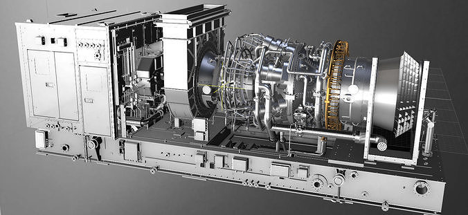
Consulting – ADVANCES IN TECHNOLOGY FOR CENTRIFUGAL COMPRESSORS

ADVANCES IN TECHNOLOGY FOR CENTRIFUGAL COMPRESSORS

ROTODYNAMIC DESIGN IN CENTRIFUGAL COMPRESSORS

DEVELOPMENT IN DRY GAS SEALS SYSTEMS

Firstly, let’s consider the lateral analysis, which is an essential component of the rotodynamic design. This analysis focuses on the evaluation of the lateral stability of the compressor’s components, such as the impeller, bearings, and casing. The analysis considers the lateral loads generated during operation and ensures that the components can withstand these loads without experiencing excessive deflection or deformation. The results of the lateral analysis are used to determine the optimal thickness and stiffness of the components, ensuring that they can withstand the lateral forces generated during operation.

Similarly, torsional analysis is also a vital aspect of the rotodynamic design. It focuses on the evaluation of the torsional stability of the compressor’s components, which can experience twisting forces during operation. These forces can lead to excessive stresses and deformation, causing critical failures or unscheduled shutdowns. Torsional analysis considers the torsional stiffness and damping of the components to ensure that they can withstand the twisting forces generated during operation.

Furthermore, stiffness and damping are also crucial considerations during the rotodynamic design. These factors affect the dynamic behavior of the compressor components, such as the impeller, shaft, and bearings, and can influence the natural frequencies of these components. The design ensures that the stiffness and damping of the components are optimized to reduce the risk of fatigue failures and vibration problems, which can lead to critical failures or unscheduled shutdowns.

The critical speed map is another essential component of the rotodynamic design. This map identifies the speeds at which the compressor is prone to resonance, which can cause severe damage or failure. The map considers the natural frequencies of the compressor components and the rotational speed of the compressor to determine the critical speeds. The design ensures that the compressor operates at speeds outside the critical speed range to prevent resonance and avoid critical failures.

Stability analysis is also essential during the rotodynamic design to ensure that the compressor operates within a stable range of flow rates and pressure ratios. The analysis considers the dynamic behavior of the compressor components and identifies the stability limits of the compressor. The design ensures that the compressor operates within these limits to avoid surging or stalling, which can lead to unscheduled shutdowns and severe damage to the compressor.

Finally, typical mode shapes are analyzed during the design phase to identify any potential resonance or vibration modes that may cause critical failures. The analysis considers the natural frequencies of the compressor components and determines the mode shapes that can lead to resonance or vibration problems. The design ensures that the compressor components are designed to avoid these modes, reducing the risk of critical failures or unscheduled shutdowns.

In conclusion, the rotodynamic design of industrial centrifugal compressors is a complex process that considers several critical factors to ensure the reliability, maintainability, and safety of the compressor. These factors include lateral and torsional analysis, stiffness, damping, critical speed map, stability analysis, and typical mode shapes. The design ensures that the compressor can operate efficiently without experiencing critical failures or unscheduled shutdowns, improving the overall performance and longevity of the compressor.

In recent years, dry gas seal systems have become increasingly popular in centrifugal compressors in the oil, gas, and petrochemical industries. These seal systems offer several advantages over other mechanical seal designs, including improved reliability, reduced maintenance requirements, and reduced risk of environmental leaks.

API 692 is a widely recognized standard for the engineering and design of dry gas seal systems for centrifugal compressors. This standard provides guidelines for the selection of suitable materials, design considerations, and testing procedures to ensure the reliability and safety of the seal system. By following these guidelines, engineers and designers can ensure that the dry gas seal system is properly designed to meet the specific operating conditions and requirements of the compressor.

One major advantage of dry gas seal systems is their ability to operate without any liquid lubrication, which eliminates the need for oil-based lubrication systems that can contribute to environmental leaks. This is particularly important in industries where environmental regulations are strict, and any leaks or spills can have significant consequences for the environment and the surrounding communities.

Another advantage of dry gas seal systems is their reduced maintenance requirements. Traditional mechanical seals require regular maintenance and replacement, which can be time-consuming and costly. Dry gas seals, on the other hand, can operate for extended periods of time without maintenance or replacement, reducing the overall lifecycle cost of the compressor.

Dry gas seals also offer improved reliability compared to other seal designs. The absence of liquid lubricants reduces the risk of seal face damage, and the seal design allows for self-cleaning of the seal faces, reducing the risk of blockages and failures. Additionally, dry gas seals are less susceptible to process upsets and contamination, which can lead to premature failures in other seal designs.

Finally, dry gas seal systems can be retrofitted to existing compressors, allowing operators to upgrade their equipment without the need for significant modifications or downtime. This can be particularly beneficial for operators looking to improve the reliability and safety of their existing equipment while minimizing disruption to their operations.

In conclusion, dry gas seal systems offer several advantages over other mechanical seal designs in terms of reliability, maintenance requirements, and environmental safety. By following the guidelines set out in API 692, engineers and designers can ensure that the dry gas seal system is properly designed to meet the specific operating conditions and requirements of the compressor, and operators can benefit from improved reliability and reduced environmental risk in both new projects and existing operating plants.

LIMITS IN ENGINEERING & DESIGN ABOUT ROTODYNAMIC ANALYSIS

LIMITS IN ENGINEERING & DESIGN IN DRY GAS SEALS SYSTEMS

While rotodynamic analysis is crucial in the engineering and design of industrial centrifugal compressors, it is important to recognize that there are limits to what can be achieved through analysis alone. The design process involves a balance of trade-offs between performance, reliability, and cost, and there are practical limitations to what can be achieved within these constraints.

One limitation of the rotodynamic analysis is the accuracy of the assumptions used in the analysis. Simplifying assumptions are often made to simplify the analysis, but these assumptions can introduce errors into the design. Additionally, the analysis is typically based on a steady-state model, which may not accurately represent the transient behavior of the compressor during start-up or shutdown. Therefore, it is essential to validate the assumptions used in the analysis through testing and modeling to ensure the accuracy of the design.

Another limitation of the rotodynamic analysis is the uncertainty in the operating conditions of the compressor. The analysis assumes a specific range of operating conditions, such as flow rate and pressure, but the actual operating conditions may vary due to changes in the process or environmental conditions. Therefore, the design must incorporate sufficient margins to account for these uncertainties to ensure the reliability and safety of the compressor.

Furthermore, there are limitations in the available materials and manufacturing processes that can affect the design of the compressor. The design must consider the mechanical properties of the materials used, such as the strength and ductility, to ensure that the compressor can withstand the loads and stresses experienced during operation. Additionally, the design must consider the manufacturing process used to produce the components, such as casting or forging, to ensure that the components can be produced with the required accuracy and quality.

Cost is also a limitation in the engineering and design of industrial centrifugal compressors. The design must balance the cost of the components, the operating costs, and the overall reliability and safety of the compressor. While a more robust design may increase the reliability and safety of the compressor, it may also increase the cost of the compressor. Therefore, the design must balance these trade-offs to achieve the desired performance and reliability while minimizing costs.

Finally, the design of the compressor must consider the maintenance and repair requirements of the compressor. While a more complex design may improve the performance and reliability of the compressor, it may also increase the complexity and cost of maintenance and repair. Therefore, the design must consider the practicality of maintaining and repairing the compressor and ensure that the design can be easily serviced and repaired when necessary.

In conclusion, while rotodynamic analysis is an essential aspect of the engineering and design of industrial centrifugal compressors, there are limitations to what can be achieved through analysis alone. The design process must balance the trade-offs between performance, reliability, cost, and practicality to achieve the desired outcomes. By considering these limitations during the design phase, the design can improve the reliability, maintainability, and safety of the compressor and reduce the risk of critical failures and unscheduled shutdowns.

While dry gas seal systems offer many advantages over other seal designs, there are some limitations that must be considered during the engineering and design phase to ensure high reliability and avoid critical failures and environmental leaks in the oil, gas, and petrochemical industries.

One major limitation is that dry gas seals require a clean and dry gas supply to operate properly. Any impurities, moisture, or other contaminants in the gas can cause damage to the seal faces and reduce the effectiveness of the seal. Therefore, it is essential to ensure that the gas supply is properly filtered and dried before it reaches the dry gas seal system. This requires careful selection of filtration and drying equipment, as well as appropriate maintenance procedures to ensure that the gas supply remains clean and dry over time.

Another limitation is the need for appropriate venting and monitoring systems to prevent the build-up of pressure or gases within the seal chamber. Excessive pressure or gas accumulation can cause seal face damage or even catastrophic failure, leading to unplanned downtime, equipment damage, and potential environmental leaks. Therefore, it is important to design the seal system with appropriate venting and monitoring systems to ensure that any pressure or gas buildup is safely vented before it can cause any damage.

Additionally, dry gas seals require more precise alignment and balancing than other seal designs. Even small misalignments or imbalances can cause increased wear and damage to the seal faces, leading to reduced reliability and increased maintenance requirements. Therefore, it is important to ensure that the compressor rotor is properly balanced and aligned during installation and that appropriate monitoring systems are in place to detect any changes in alignment or balance over time.

Finally, dry gas seal systems may not be suitable for all types of applications or operating conditions. In some cases, other seal designs may be more appropriate, depending on factors such as the gas composition, pressure, temperature, and flow rates. Therefore, it is important to carefully consider the specific operating conditions and requirements of the compressor when selecting the appropriate seal system.

In conclusion, while dry gas seal systems offer many benefits in terms of reliability and environmental safety, there are also several limitations that must be considered during the engineering and design phase to ensure high reliability and avoid critical failures and environmental leaks in the oil, gas, and petrochemical industries. By carefully selecting appropriate equipment, designing appropriate venting and monitoring systems, ensuring proper alignment and balancing, and considering the specific operating conditions and requirements of the compressor, engineers and designers can ensure that the dry gas seal system is properly designed to meet the specific needs of the application.

CRITICAL RISKS IN BAD ROTODYNAMIC ANALYSIS OR STUDIES CAUSING FAILURES

PROCEDURES, ACTIONS, STUDIES, MITIGATIONS, RECOMMENDATIONS TO GET HIGH RELIABILITY IN DGS SYSTEMS

Inadequate rotodynamic studies or analysis can pose critical risks to the reliability, maintainability, and safety of industrial centrifugal compressors, which can lead to critical failures and unscheduled shutdowns. These risks can arise due to a number of factors, including errors in the assumptions made during the analysis, insufficient consideration of the operating conditions and environmental factors, and a lack of understanding of the mechanical properties of the materials used in the compressor.

One critical risk of bad rotodynamic studies is the failure to accurately predict the critical speed of the compressor. The critical speed is the rotational speed at which the natural frequency of the rotor coincides with the frequency of one or more modes of vibration, leading to excessive vibrations and potentially catastrophic failures. Inaccurate predictions of the critical speed can result in the selection of a rotor that is not properly designed to avoid resonance, leading to dangerous levels of vibrations and potential failures.

Another critical risk of bad rotodynamic studies is the failure to properly account for lateral and torsional vibrations in the compressor. These vibrations can result in excessive stresses on the compressor components, leading to fatigue failure and reduced reliability. Additionally, if the compressor is not properly designed to avoid resonance, these vibrations can lead to excessive wear on the bearings and other components, reducing the overall lifespan of the compressor.

Insufficient consideration of damping and stiffness can also pose critical risks to the reliability and safety of the compressor. Damping is essential in reducing the amplitude of vibrations in the compressor, while stiffness is crucial in maintaining the integrity of the compressor under operating loads. If these factors are not properly accounted for in the analysis, the compressor may be subject to excessive vibrations and stresses that can lead to critical failures.

Finally, bad rotodynamic studies can result in the selection of materials and manufacturing processes that are not suitable for the operating conditions of the compressor. For example, if the compressor is operating in a corrosive environment, the selection of materials that are not resistant to corrosion can lead to premature failure of the compressor components. Similarly, if the manufacturing process used to produce the components is not capable of producing components with the required accuracy and quality, the resulting compressor may not perform as expected and may be subject to premature failure.

In conclusion, the risks of bad rotodynamic studies or analysis in industrial centrifugal compressors can have serious consequences for the reliability, maintainability, and safety of the compressor, leading to critical failures and unscheduled shutdowns. By properly accounting for factors such as critical speed, lateral and torsional vibrations, damping and stiffness, and materials selection and manufacturing processes during the engineering and design phase, the risks of these failures can be mitigated, and the overall reliability and safety of the compressor can be improved.

To ensure high reliability and avoid critical failures and environmental leaks in dry gas seal systems for centrifugal compressors, several procedures, actions, studies, mitigations, and recommendations can be applied during the engineering and design phase and throughout the lifecycle of the equipment.

  1. Gas Supply Preparation: One of the critical steps in ensuring the reliability of dry gas seal systems is to prepare the gas supply. This involves the filtration and drying of gas before it enters the dry gas seal system. The gas supply should be free from contaminants, moisture, and other impurities to prevent damage to the seal faces.

  2. Venting and Monitoring Systems: Proper venting and monitoring systems should be in place to prevent the build-up of pressure or gases within the seal chamber. An accumulation of pressure or gas can lead to seal face damage or catastrophic failure, leading to equipment damage, unplanned downtime, and potential environmental leaks.

  3. Alignment and Balancing: Proper alignment and balancing of the compressor rotor are crucial to ensure the longevity of the dry gas seal system. Even a small misalignment or imbalance can cause increased wear and damage to the seal faces, leading to reduced reliability and increased maintenance requirements. Therefore, it is important to ensure that the compressor rotor is correctly balanced and aligned during installation and appropriate monitoring systems are in place to detect any changes in alignment or balance over time.

  4. Maintenance and Inspection: Regular maintenance and inspection of the dry gas seal system are necessary to ensure its reliability and longevity. Maintenance tasks may include replacing damaged or worn seal faces, monitoring seal performance, and inspecting the venting and monitoring systems.

  5. Risk Assessment and Mitigation: A risk assessment should be conducted to identify potential hazards and risks associated with the dry gas seal system. Appropriate mitigation measures should be taken to reduce the likelihood of failure and to minimize the consequences of any failure.

  6. Material Selection: The selection of appropriate materials for the dry gas seal system is crucial to ensure the longevity and reliability of the system. The selection of materials should take into account factors such as the gas composition, temperature, and pressure, as well as the operating conditions and requirements of the compressor.

  7. Training and Education: Proper training and education for operators and maintenance personnel are critical to ensuring the reliable operation of the dry gas seal system. Operators and maintenance personnel should be knowledgeable about the design and operation of the dry gas seal system and should be trained to detect and respond to any potential issues or malfunctions.

In conclusion, to ensure high reliability and avoid critical failures and environmental leaks in dry gas seal systems for centrifugal compressors, several procedures, actions, studies, mitigations, and recommendations can be applied during the engineering and design phase and throughout the lifecycle of the equipment. By taking appropriate measures, engineers and designers can ensure the safe and reliable operation of the dry gas seal system in the oil, gas, and petrochemical industries.

courtesy by BAKER HUGHES

ADVANCES IN SUBSEA COMPRESSION SYSTEMS

RESONANCE & STRUCTURAL PROBLEMS IN CENTRIFUGAL COMPRESSORS

Subsea compression systems using centrifugal compressors have experienced significant advances in recent years, leading to improvements in reliability, safety, and environmental protection.

One of the main benefits of subsea compression systems is that they allow for the compression of gas at the wellhead, reducing the need for complex and expensive surface facilities. This results in cost savings and improved operational efficiency.

Advances in engineering and design have enabled the development of highly reliable subsea compression systems. For example, the use of dry gas seals instead of traditional mechanical seals has greatly reduced the risk of environmental leaks. Additionally, the development of subsea variable frequency drives has improved the efficiency and performance of subsea compressors, while also reducing the need for maintenance.

In terms of mitigating risks, thorough studies and simulations are performed during the design phase to identify potential hazards and assess the performance of the system under different operating conditions. This includes analyzing the effects of temperature and pressure fluctuations, as well as the impact of water depth and subsea currents.

Recommendations for improving reliability in subsea compression systems include the use of advanced materials and coatings to protect against corrosion, the incorporation of redundant systems and sensors to improve fault tolerance, and the implementation of advanced control systems to optimize performance and minimize downtime.

Overall, the advances made in subsea compression systems using centrifugal compressors have greatly improved the reliability and safety of these systems, making them an attractive option for new projects and existing plants in the oil, gas, and petrochemical industries.

Resonance is a critical problem associated with centrifugal compressors that can cause mechanical and structural issues leading to failures and environmental hazards. Resonance is a condition where the natural frequency of the compressor or its components matches with the frequency of the vibrations induced by the compressor operation. This can lead to amplified vibrations, which can cause fatigue and wear and tear of the compressor components, leading to mechanical failure.

Resonance can occur due to various reasons, such as improper design, inadequate material selection, incorrect assembly, or changes in the operating conditions. The resonance can occur in various parts of the compressor, such as the impeller, shaft, bearings, seals, and foundation. The resonance of the impeller and shaft can cause high stresses leading to cracking and ultimately failure. Resonance of the bearings can cause excessive wear and tear, leading to premature failure.

The resonance can also affect the foundation of the compressor, leading to structural damage and leakage of the process fluid. The leakage of the process fluid can cause environmental hazards and safety risks to the workers in the plant.

To avoid resonance-related issues, it is crucial to perform thorough engineering and design studies during the design phase of the compressor. The studies should include dynamic analysis, modal analysis, and frequency response analysis to identify and mitigate potential resonance issues. Material selection, assembly procedures, and operating conditions should also be carefully considered to avoid resonance-related failures.

During the maintenance and operation phase, it is essential to monitor the compressor’s vibrations regularly and perform vibration analysis to detect and diagnose any resonance-related issues. Any potential issues should be addressed promptly to avoid critical failures and environmental hazards. It is also crucial to train the plant personnel in resonance-related issues and provide them with proper procedures and tools to mitigate the risks.

LIMITS IN ENGINEERING & DESIGN FOR SUBSEA COMPRESSION SYSTEMS

LIMITS IN ENGINEERING & DESIGN ABOUT RESONANCE & STRUCTURAL PROBLEMS IN CENT. COMPRESSORS

Despite the advancements in subsea compression systems using centrifugal compressors, there are still limits in engineering and design that must be considered to ensure the reliability and safety of these systems.

One limitation is the need for regular maintenance and inspection of subsea components, which can be challenging due to the remote location and harsh operating conditions. Access to subsea equipment is limited and maintenance activities may require specialized tools and equipment, as well as experienced personnel.

Another limitation is the impact of environmental factors such as water depth, temperature, and pressure on the performance of the system. These factors can affect the reliability and efficiency of the subsea compression system, and must be carefully considered during the design phase to ensure that the system can operate safely and effectively under a range of conditions.

Furthermore, subsea compression systems are often subject to stringent regulatory requirements to ensure environmental protection, which may impose additional design and operational limitations. For example, regulations may require the use of certain materials or the implementation of specific safety features to prevent environmental leaks.

In order to mitigate these limitations and improve the reliability and safety of subsea compression systems, engineers and designers must carefully consider the design and operation of the system. This may include the use of advanced materials and coatings to protect against corrosion, the incorporation of redundant systems and sensors to improve fault tolerance, and the implementation of advanced control systems to optimize performance and minimize downtime. In addition, regular maintenance and inspection of subsea equipment is essential to ensure the continued safe and effective operation of the system.

The limits in engineering and design associated with resonance, mechanical, and structural issues using centrifugal compressors are crucial to ensuring high reliability and preventing critical failures in oil, gas, and petrochemical industries. These limits can include limitations in materials selection, design, and manufacturing processes that can affect the compressor’s mechanical and structural integrity.

One of the primary limitations is the selection of materials for the compressor components. The materials used must have high fatigue resistance and be able to withstand high stress levels, especially in areas prone to resonance, such as impellers and shafts. The design must also consider factors such as manufacturing tolerances, surface roughness, and other mechanical properties that can affect the compressor’s performance and reliability.

Another limitation is the design of the compressor system to avoid resonant frequencies that can cause excessive vibration and damage to the components. This includes selecting an appropriate compressor speed, blade count, and spacing to avoid excitation of resonant frequencies. Adequate damping and stiffness must also be designed into the system to prevent vibration and other structural issues.

Furthermore, proper maintenance and operation practices must be established to ensure the continued reliability of the compressor. This includes regular inspections, monitoring of vibration levels, and timely repairs or replacements of components as needed.

In summary, the limits in engineering and design associated with resonance, mechanical, and structural issues using centrifugal compressors include materials selection, design considerations, and proper maintenance and operation practices. These limitations must be carefully considered to improve the reliability and prevent critical failures in new projects and existing plants in oil, gas, and petrochemical industries.

PROCEDURES, ACTIONS, STUDIES, RECOMMENDATIONS, AND CRITICAL RISKS IN SUBSEA COMPRESSION SYSTEMS

CRITICAL RISKS AND PROCEDURES, ACTIONS, STUDIES, MITIGATION AND RECOMMENDATIONS IN RESONACE & STRUCTURAL PROBLEMS

Subsea compression systems using centrifugal compressors face a range of critical risks and potential failures that can impact the reliability, safety, and environmental impact of the system. These risks and failures must be carefully managed through a range of procedures, actions, studies, mitigations, and recommendations to ensure that the system can operate safely and effectively over its entire lifecycle.

One critical risk for subsea compression systems is the potential for environmental leaks, which can have severe consequences for marine life and the surrounding ecosystem. To mitigate this risk, the system should be designed with multiple barriers and redundancies to prevent leaks from occurring. In addition, regular inspection and maintenance should be conducted to identify and address potential leaks before they become a critical issue.

Another critical risk is the potential for equipment failure due to harsh operating conditions and the remote location of subsea components. To address this risk, the system should be designed with a high degree of fault tolerance and redundancy, including multiple compressors and other critical components. Regular maintenance and inspection should also be conducted to identify and address potential failures before they result in a system shutdown or critical failure.

To improve the reliability, maintenance, and operation of subsea compression systems using centrifugal compressors, a range of procedures, actions, studies, and recommendations should be implemented. These may include:

  • Conducting detailed engineering and design studies to optimize the system for the specific operating conditions and environmental factors that will be encountered.
  • Incorporating advanced monitoring and control systems to optimize performance and reduce downtime.
  • Implementing regular maintenance and inspection procedures to identify and address potential issues before they become critical.
  • Conducting risk assessments and contingency planning to prepare for potential failures and minimize their impact on the system.
  • Implementing advanced communication systems to enable remote monitoring and control of subsea equipment, reducing the need for personnel to access the site in person.
  • Conducting regular training and competency assessments for personnel involved in the operation and maintenance of the system to ensure that they are able to perform their duties safely and effectively.

By implementing these procedures, actions, studies, and recommendations, subsea compression systems using centrifugal compressors can achieve high levels of reliability, safety, and environmental performance, reducing the risk of critical failures and unscheduled shutdowns, and helping to protect the surrounding ecosystem.

The critical risks associated with resonance, mechanical and structural issues in centrifugal compressors include increased vibrations leading to mechanical failure, decreased efficiency and increased maintenance costs. Additionally, resonance can cause severe structural damage to the compressor and surrounding equipment.

To mitigate these risks, it is essential to conduct thorough engineering and design studies, including finite element analysis (FEA) and modal analysis, to identify potential resonance and mechanical issues. These studies should be carried out during the design phase and continuously throughout the operation of the compressor.

Procedures for mitigating these risks include the installation of vibration monitoring systems and regular inspections of the compressor and its surrounding equipment to identify any early signs of resonance, mechanical or structural issues. The use of appropriate material selection and robust design principles, such as avoiding critical speed zones and ensuring adequate stiffness and damping, can also help prevent resonance issues.

It is recommended to carry out regular maintenance on the compressor, including vibration analysis, lubrication analysis, and mechanical inspections to detect and prevent any issues that could lead to resonance. Additionally, it is essential to train personnel to recognize the early warning signs of resonance and take corrective actions before they escalate into critical failures.

Overall, it is critical to prioritize reliability in the design, maintenance, and operation of centrifugal compressors to avoid resonance-related risks and ensure the safety and efficiency of oil, gas and petrochemical plants.

Consulting – ADVANCES IN TECHNOLOGY FOR CENTRIFUGAL COMPRESSORS Leer más »